Материал: 1n5819

DISCRETE SEMICONDUCTORS
page
M3D119
1N5817; 1N5818; 1N5819
Schottky barrier diodes
Product specification |
1996 May 03 |
Supersedes data of April 1992
File under Discrete Semiconductors, SC01
Philips Semiconductors |
Product specification |
|
|
|
|
Schottky barrier diodes |
1N5817; 1N5818; 1N5819 |
|
|
|
|
FEATURES
∙Low switching losses
∙Fast recovery time
∙Guard ring protected
∙Hermetically sealed leaded glass package.
APPLICATIONS
∙Low power, switched-mode power supplies
∙Rectifying
∙Polarity protection.
DESCRIPTION
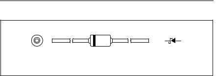
The 1N5817 to 1N5819 types are Schottky barrier diodes fabricated in planar technology, and encapsulated in SOD81 hermetically sealed glass packages incorporating ImplotecTM(1) technology.
(1) Implotec is a trademark of Philips.
handbook, 4 columns |
k |
a |
|
|
MAM218
Fig.1 Simplified outline (SOD81) and symbol.
1996 May 03 |
2 |

Philips Semiconductors |
|
|
Product specification |
|||
|
|
|
|
|
|
|
Schottky barrier diodes |
1N5817; 1N5818; 1N5819 |
|||||
|
|
|
|
|
|
|
LIMITING VALUES |
|
|
|
|
|
|
In accordance with the Absolute Maximum Rating System (IEC 134). |
|
|
|
|
||
|
|
|
|
|
|
|
SYMBOL |
PARAMETER |
CONDITIONS |
MIN. |
|
MAX. |
UNIT |
|
|
|
|
|
|
|
VR |
continuous reverse voltage |
|
|
|
|
|
|
1N5817 |
|
− |
|
20 |
V |
|
1N5818 |
|
− |
|
30 |
V |
|
1N5819 |
|
− |
|
40 |
V |
|
|
|
|
|
|
|
VRSM |
non-repetitive peak reverse voltage |
|
|
|
|
|
|
1N5817 |
|
− |
|
24 |
V |
|
1N5818 |
|
− |
|
36 |
V |
|
1N5819 |
|
− |
|
48 |
V |
|
|
|
|
|
|
|
VRRM |
repetitive peak reverse voltage |
|
|
|
|
|
|
1N5817 |
|
− |
|
20 |
V |
|
1N5818 |
|
− |
|
30 |
V |
|
1N5819 |
|
− |
|
40 |
V |
|
|
|
|
|
|
|
VRWM |
crest working reverse voltage |
|
|
|
|
|
|
1N5817 |
|
− |
|
20 |
V |
|
1N5818 |
|
− |
|
30 |
V |
|
1N5819 |
|
− |
|
40 |
V |
|
|
|
|
|
|
|
IF(AV) |
average forward current |
Tamb = 55 °C; Rth j-a = 100 K/W; |
− |
|
1 |
A |
|
|
note 1; VR(equiv) = 0.2 V; note 2 |
|
|
|
|
IFSM |
non-repetitive peak forward current |
t = 8.3 ms half sine wave; |
− |
|
25 |
A |
|
|
JEDEC method; |
|
|
|
|
|
|
Tj = Tj max prior to surge: VR = 0 |
|
|
|
|
Tstg |
storage temperature |
|
−65 |
|
+175 |
°C |
Tj |
junction temperature |
|
− |
|
125 |
°C |
Notes
1.Refer to SOD81 standard mounting conditions.
2.For Schottky barrier diodes thermal run-away has to be considered, as in some applications, the reverse power
losses PR are a significant part of the total power losses. Nomograms for determination of the reverse power losses PR and IF(AV) rating will be available on request.
1996 May 03 |
3 |

Philips Semiconductors |
|
|
|
|
Product specification |
||||
|
|
|
|
|
|
|
|
|
|
Schottky barrier diodes |
|
1N5817; 1N5818; 1N5819 |
|||||||
|
|
|
|
|
|
|
|
|
|
ELECTRICAL CHARACTERISTICS |
|
|
|
|
|
|
|
||
Tamb = 25 °C; unless otherwise specified. |
|
|
|
|
|
|
|
||
|
|
|
|
|
|
|
|
|
|
SYMBOL |
PARAMETER |
CONDITIONS |
|
MIN. |
TYP. |
|
MAX. |
UNIT |
|
|
|
|
|
|
|
|
|
|
|
VF |
forward voltage |
see Fig.2 |
|
|
|
|
|
|
|
|
1N5817 |
IF = 0.1 A |
|
− |
− |
|
320 |
mV |
|
|
|
|
IF = 1 A |
|
− |
− |
|
450 |
mV |
|
|
|
IF = 3 A |
|
− |
− |
|
750 |
mV |
VF |
forward voltage |
see Fig.2 |
|
|
|
|
|
|
|
|
1N5818 |
IF = 0.1 A |
|
− |
− |
|
330 |
mV |
|
|
|
|
IF = 1 A |
|
− |
− |
|
550 |
mV |
|
|
|
IF = 3 A |
|
− |
− |
|
875 |
mV |
VF |
forward voltage |
see Fig.2 |
|
|
|
|
|
|
|
|
1N5819 |
IF = 0.1 A |
|
− |
− |
|
340 |
mV |
|
|
|
|
IF = 1 A |
|
− |
− |
|
600 |
mV |
|
|
|
IF = 3 A |
|
− |
− |
|
900 |
mV |
IR |
reverse current |
VR = VRRMmax; note 1 |
|
− |
− |
|
1 |
mA |
|
|
|
|
VR = VRRMmax; Tj = 100 °C |
|
− |
− |
|
10 |
mA |
Cd |
diode capacitance |
VR = 4 V; f = 1 MHz |
|
|
|
|
|
|
|
|
1N5817 |
|
|
− |
80 |
|
− |
pF |
|
|
1N5818 |
|
|
− |
50 |
|
− |
pF |
|
|
1N5819 |
|
|
− |
50 |
|
− |
pF |
|
|
|
|
|
|
|
|
|
|
|
Note
1. Pulsed test: tp = 300 μs; δ = 0.02.
THERMAL CHARACTERISTICS
SYMBOL |
PARAMETER |
CONDITIONS |
VALUE |
UNIT |
|
|
|
|
|
Rth j-a |
thermal resistance from junction to ambient |
note 1 |
100 |
K/W |
Note |
|
|
|
|
1. Refer to SOD81 standard mounting conditions.
1996 May 03 |
4 |
Philips Semiconductors |
|
|
|
|
|
|
|
|
|
|
|
|
Product specification |
||||
|
|
|
|
|
|
|
|
|
|
|
|
|
|
|
|
|
|
Schottky barrier diodes |
|
|
|
|
|
|
|
1N5817; 1N5818; 1N5819 |
|||||||||
|
|
|
|
|
|
|
|
|
|
|
|
|
|
|
|
|
|
GRAPHICAL DATA |
|
|
|
|
|
|
|
|
|
|
|
|
|
||||
|
|
|
|
|
|
|
|
|
|
|
|
|
|
|
|
||
5 |
|
|
|
|
|
|
|
|
|
|
|
MBE634 |
|
|
|
||
|
|
|
|
|
|
|
|
|
|
|
|
|
|
|
|
|
|
handbook, halfpage |
|
|
|
|
|
|
|
|
|
|
|
|
|
|
|
|
|
IF |
|
|
|
|
|
|
|
|
|
|
|
|
|
|
|
|
|
(A) |
|
|
|
Tj |
|
= 125 |
|
oC |
|
|
25 o |
C |
|
|
|
|
|
4 |
|
|
|
|
|
|
|
|
|
|
|
|
|
|
|||
|
|
|
|
|
|
|
|
|
|
|
|
|
|
|
|
|
|
3 |
|
|
|
|
|
|
|
|
|
|
|
|
|
|
|
|
|
|
|
|
|
|
|
|
|
|
|
|
|
|
|
|
|
|
|
|
|
|
|
|
|
|
|
|
|
|
|
|
|
|
|
|
|
2 |
|
|
|
|
|
|
|
|
|
|
|
|
|
|
|
|
|
|
|
|
|
|
|
|
|
|
|
|
|
|
|
|
|
|
|
|
|
|
|
|
|
|
|
|
|
|
|
|
|
|
|
|
|
1 |
|
|
|
|
|
|
|
|
|
|
|
|
|
|
|
|
|
|
|
|
|
|
|
|
|
|
|
|
|
|
|
|
|
|
|
|
|
|
|
|
|
|
|
|
|
|
|
|
|
|
|
|
|
0 |
|
|
|
|
|
|
|
|
|
|
|
|
|
|
|
|
|
|
|
|
|
|
|
|
|
|
|
|
|
|
|
|
|
|
|
|
|
|
|
0.5 |
|
|
VF (V) |
|
|
|
|||||||
0 |
|
|
|
|
|
1 |
|
||||||||||
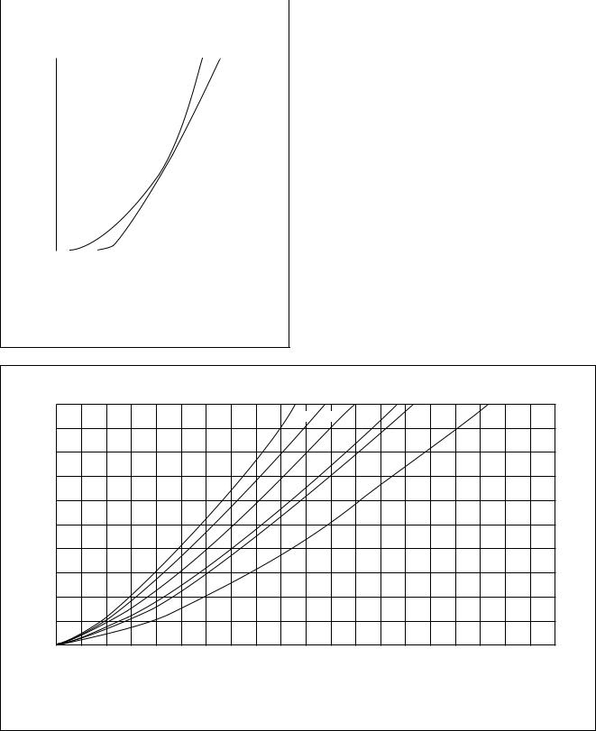
Fig.2 Typical forward voltage.
MBE642
1
a = 3 |
2.5 |
2 |
1.57 |
1.42 |
1 |
PF(AV)
(W)
0.5
0 |
|
|
|
|
|
|
0 |
0.5 |
1 |
1.5 |
IF(AV) |
(A) |
2 |
|
|
|
|
|
Fig.3 1N817. Maximum values steady state forward power dissipation as a function of the average forward current; a = IF(RMS)/IF(AV).
1996 May 03 |
5 |