Материал: 7

FAST AND LS TTL
Package Information
Including 7
Surface Mount
BIPOLAR LOGIC SURFACE MOUNT
WHY SURFACE MOUNT?
Surface Mount Technology is now being utilized to offer answers to many problems that have been created in the use of insertion technology.
Limitations have been reached with insertion packages and PC board technology. Surface Mount Technology offers the opportunity to continue to advance the State-of-the-Art designs that cannot be accomplished with Insertion Technology.
Surface Mount Packages allow more optimum device performance with the smaller Surface Mount configuration. Internal lead lengths, parasitic capacitance and inductance that placed limitations on chip performance have been reduced.
The lower profile of Surface Mount Packages allows more boards to be utilized in a given amount of space. They are stacked closer together and utilize less total volume than insertion populated PC boards.
Printed circuit costs are lowered with the reduction of the number of board layers required. The elimination or reduction of the number of plated through holes in the board, contribute significantly to lower PC board prices.
Surface Mount assembly does not require the preparation of components that are common on insertion technology lines.
Surface Mount components are sent directly to the assembly line, eliminating an intermediate step.
Automatic placement equipment is available that can place Surface Mount components at the rate of a few thousand per hour to hundreds of thousands of components per hour.
Surface Mount Technology is cost effective, allowing the manufacturer the opportunity to produce smaller units and/or offer increased functions with the same size product.
SURFACE MOUNT AVAILABILITY
Bipolar Logic is currently offering LS-TTL and FAST-TTL in production quantities in SOIC packages.
Refer to the following Selector Guide (SG366/D) which indicate availability and package type for these families.
These families may be ordered in rails or on Tape and Reel. Refer to Tape and Reel information for ordering details.
THERMAL DATA
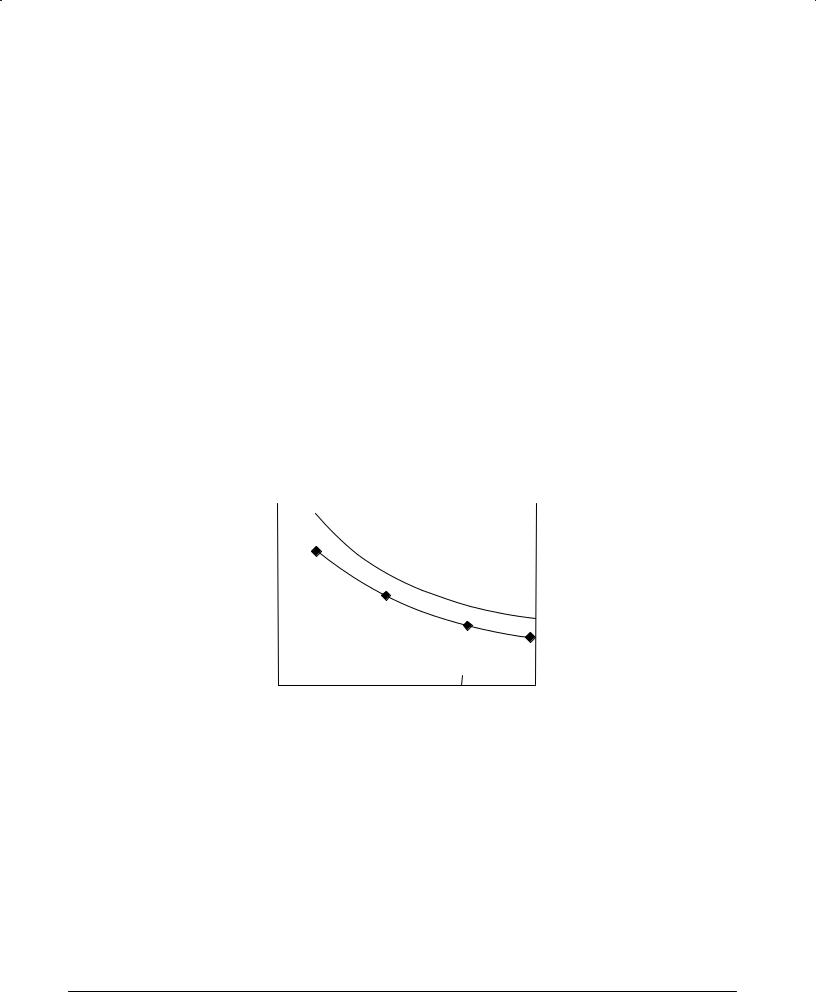
The power dissipation of surface mount packages is dependent on many factors that must be taken into consideration in the initial board design. The board material, the board surface metal thickness, pad area and the proximity to other heat generating components all have a bearing on the device dissipation capability.
200 |
|
|
|
|
|
|
|
|
|
|
|
|
|
|
|
|
|
|
|
|
|
180 |
|
|
|
|
|
|
|
|
|
|
|
|
|
|
|
|
|
|
|
|
|
160 |
|
|
|
|
|
|
MIN DIE SIZE |
|
|
|
|
|
|
|
|
|
|
|
|||
°C/W |
|
|
|
|
|
|||||
qJA |
|
|
|
|
2K MILS2 |
|
|
|||
|
|
|
|
|
|
|
||||
140 |
|
|
|
|
|
|
MAX DIE SIZE |
|
|
|
|
|
|
|
|
|
|
|
|||
120 |
|
|
|
|
|
|
|
|
||
|
|
|
|
|
|
|
|
|||
|
|
|
|
|
SEE FIG. 2 FOR |
8K MILS2 |
|
|
||
100 |
|
|
|
|
HEAT SINK DETAIL |
|
|
|
|
|
|
|
|
|
|
|
|
|
|||
|
SO-8 |
LEADFRAME |
SO-14 |
SO-16 |
||||||
|
|
|||||||||
|
|
(.090″ x .110″ ) |
METAL = COPPER |
(.090″ |
x .170″ ) |
(.090″ |
x .170″ ) |
|||
NARROW
PACKAGE STYLE
DATA TAKEN USING PHILIPS SO TEST BOARD # 7322-078, 80873
Figure 2-1. Thermal Resistance, Junction-To-Ambient (°C/W)
Measurement specimens are solder mounted on printed circuit card 19 mm × 28 mm × 1.5 mm in still air. No auxiliary thermal condition aids are used.
This data was collected using thermal test die in 20-pin PLCC packages on PLCC test boards (2.24″ x 2.24″ x .062″ glass epoxy, type FR-4, with solder coated 1 oz./sq. ft. copper).
FAST AND LS TTL DATA
7-2
TAPE AND REEL
STANDARD BIPOLAR LOGIC INTEGRATED CIRCUITS
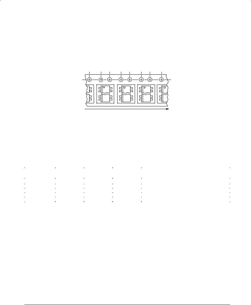
Motorola has now added the convenience of Tape and Reel packaging for our growing family of standard Integrated Circuit products. The packaging fully conforms to the latest EIA
RS-481A specification. The antistatic embossed tape provides a secure cavity sealed with a peel-back cover tape.
MECHANICAL POLARIZATION
SOIC DEVICES
Typical
View is from tape side
|
Linear direction of travel |
GENERAL INFORMATION |
|
Ð Reel Size |
13 inch (330 mm) Suffix R2 |
Ð Tape Width |
12 mm to 24 mm (see table) |
Ð Units/Reel |
(see table) |
Ð No Partial Reel Counts Available and Minimum Lot Size is Per Table
ORDERING INFORMATION
To order devices which are to be delivered in Tape and Reel, add the suffix R2 to the device number being ordered.
TABLE 2.1 Tape and Reel Data
|
Tape Width |
|
Reel Size |
Min Lot Size Per Part No. |
Device Type |
(mm) |
Device/Reel |
(inch) |
Tape and Reel |
|
|
|
|
|
SO-8 |
12 |
2,500 |
13 |
5,000 |
SO-14 |
16 |
2,500 |
13 |
5,000 |
SO-16 |
16 |
2,500 |
13 |
5,000 |
SO-16 Wide |
16 |
1,000 |
13 |
5,000 |
SO-20 Wide |
24 |
1,000 |
13 |
5,000 |
|
|
|
|
|
FAST AND LS TTL DATA
7-3
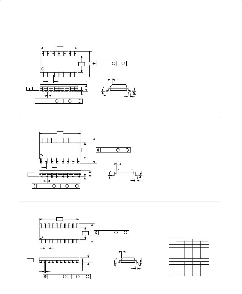
PACKAGE OUTLINES
SOIC
Case 751A-02 D Suffix
14-Pin Plastic
SO-14
-A- |
14 8
-B- |
P |
0.25 (0.010) M B M |
1 |
|
7 PL |
7 |
|
|
|
G |
C |
R X 45° |
|
|
|
|
||
|
K |
SEATING |
|
J |
|
PLANE |
|
||
D14 PL |
|
M |
F |
|


 0.25 (0.010) M T B S A S
NOTES:
1.DIMENSIONS ªAº AND ªBº ARE DATUMS AND ªTº IS A DATUM SURFACE.
2.DIMENSIONING AND TOLERANCING PER ANSI Y14.5M, 1982.
3.CONTROLLING DIMENSION: MILLIMETER.
4.DIMENSION A AND B DO NOT INCLUDE MOLD PROTRUSION.
5.MAXIMUM MOLD PROTRUSION 0.15 (0.006) PER SIDE.
6.751A-01 IS OBSOLETE, NEW STANDARD
751A-02.
|
MILLIMETERS |
INCHES |
||
DIM |
MIN |
MAX |
MIN |
MAX |
A |
8.55 |
8.75 |
0.337 |
0.344 |
B |
3.80 |
4.00 |
0.150 |
0.157 |
C |
1.35 |
1.75 |
0.054 |
0.068 |
D |
0.35 |
0.49 |
0.014 |
0.019 |
F |
0.40 |
1.25 |
0.016 |
0.049 |
G |
1.27 |
BSC |
0.050 |
BSC |
J |
0.19 |
0.25 |
0.008 |
0.009 |
K |
0.10 |
0.25 |
0.004 |
0.009 |
M |
0° |
7° |
0° |
7° |
P |
5.80 |
6.20 |
0.229 |
0.244 |
R |
0.25 |
0.50 |
0.010 |
0.019 |
Case 751B-03 D Suffix
16-Pin Plastic
SO-16
|
-A- |
16 |
9 |
|
-B- |
P |
0.25 (0.010) M |
B M |
|
1 |
8 |
8 PL |
|
|
|
|
|
|
|
|
|
G |
|
|
|
R X 45° |
|
|
C |
|
|
|
|
-T- |
|
SEATING |
|
|
|
|
|
M |
|
J |
|
D16 PL |
|
PLANE |
F |
||
|
K |
|
|
||
0.25 (0.010) M T B S |
A S |
|
|
|
|
NOTES:
1.DIMENSIONING AND TOLERANCING PER ANSI Y14.5M, 1982.
2.CONTROLLING DIMENSION: MILLIMETER.
3.DIMENSION A AND B DO NOT INCLUDE MOLD PROTRUSION.
4.MAXIMUM MOLD PROTRUSION 0.15 (0.006) PER SIDE.
5.751B-01 IS OBSOLETE, NEW STANDARD
751B-03.
|
MILLIMETERS |
INCHES |
||
DIM |
MIN |
MAX |
MIN |
MAX |
A |
9.80 |
10.00 |
0.386 |
0.393 |
B |
3.80 |
4.00 |
0.150 |
0.157 |
C |
1.35 |
1.75 |
0.054 |
0.068 |
D |
0.35 |
0.49 |
0.014 |
0.019 |
F |
0.40 |
1.25 |
0.016 |
0.049 |
G |
1.27 |
BSC |
0.050 |
BSC |
J |
0.19 |
0.25 |
0.008 |
0.009 |
K |
0.10 |
0.25 |
0.004 |
0.009 |
M |
0° |
7° |
0° |
7° |
P |
5.80 |
6.20 |
0.229 |
0.244 |
R |
0.25 |
0.50 |
0.010 |
0.019 |
|
|
|
Case 751D-03 DW Suffix |
NOTES: |
||
|
|
|
20-Pin Plastic |
|||
|
|
|
1. |
DIMENSIONING AND TOLERANCING PER ANSI |
||
|
|
|
SO-20 (WIDE) |
|||
|
|
|
|
Y14.5M, 1982. |
||
|
-A- |
|
|
|
2. |
CONTROLLING DIMENSION: MILLIMETER. |
|
|
|
|
|
3. |
DIMENSION A AND B DO NOT INCLUDE MOLD |
|
|
|
|
|
|
PROTRUSION. |
20 |
11 |
|
|
|
4. |
MAXIMUM MOLD PROTRUSION 0.15 (0.006) PER |
|
|
|
|
SIDE. |
||
|
|
|
0.25 (0.010) M |
B M |
|
|
|
-B- |
P |
5. |
751D-01, AND -02 OBSOLETE, NEW STANDARD |
||
|
|
|
|
|
|
751D-03. |
1 |
10 |
10 PL |
|
|
|
MILLIMETERS |
INCHES |
||
|
|
|
|
|
|
||||
|
|
|
|
|
DIM |
MIN |
MAX |
MIN |
MAX |
G |
|
|
|
|
A |
12.65 |
12.95 |
0.499 |
0.510 |
|
|
R X 45° |
|
B |
7.40 |
7.60 |
0.292 |
0.299 |
|
|
|
|
|
C |
2.35 |
2.65 |
0.093 |
0.104 |
|
|
|
|
|
|
D |
0.35 |
0.49 |
0.014 |
0.019 |
-T- |
|
C SEATING |
|
|
F |
0.50 |
0.90 |
0.020 |
0.035 |
|
|
|
G |
1.27 BSC |
0.050 BSC |
||||
|
|
|
|
|
|||||
|
|
PLANE |
|
|
J |
0.25 |
0.32 |
0.010 |
0.012 |
|
|
|
|
K |
0.10 |
0.25 |
0.004 |
0.009 |
|
|
|
M |
F |
J |
|||||
|
|
M |
0° |
7° |
0° |
7° |
|||
|
|
K |
|
||||||
D 20 PL |
|
|
|
P |
10.05 |
10.55 |
0.395 |
0.415 |
|
|
|
|
|
R |
0.25 |
0.75 |
0.010 |
0.029 |
|
0.25 (0.010) M |
T B S |
A S |
|
|
|||||
|
|
|
|
|
|
|
|||
FAST AND LS TTL DATA
7-4
|
|
|
|
|
|
PACKAGE OUTLINES |
|
|
|
|
|
||||
|
|
|
|
|
|
|
|
SOIC (continued) |
|
|
|
|
|
|
|
|
|
|
|
|
|
|
|
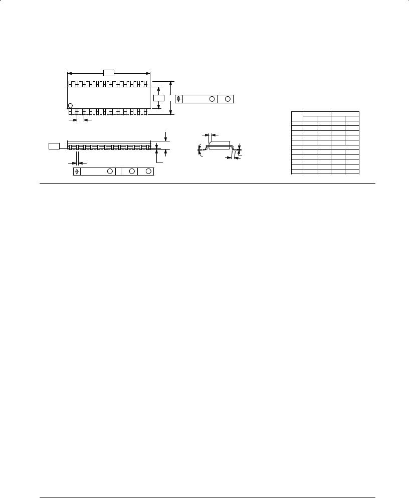
Case 751E-03 DW Suffix |
|
|
|
|
|
|
|
|
|
|
|
|
|
|
|
24-Pin Plastic |
NOTES: |
|
|
|
|
||
|
|
|
|
|
|
|
|
SO-24 (WIDE) |
|
|
|
|
|||
-A- |
|
|
|
|
|
|
1. |
DIMENSIONING AND TOLERANCING PER ANSI |
|||||||
|
|
|
|
|
|
|
|
|
Y14.5M, 1982. |
|
|
|
|||
|
|
|
|
|
|
|
|
|
|
2. |
CONTROLLING DIMENSION: MILLIMETER. |
||||
|
|
|
|
|
|
|
|
|
|
3. DIMENSION A AND B DO NOT INCLUDE MOLD |
|||||
24 |
|
|
|
|
13 |
|
|
|
|
|
PROTRUSION. |
|
|
|
|
|
|
|
|
|
|
|
|
4. MAXIMUM MOLD PROTRUSION 0.15 (0.006) |
|||||||
|
|
|
|
|
|
|
|
|
|
||||||
|
|
|
|
|
|
-B- |
P |
0.25 (0.010) M |
B M |
|
PER SIDE. |
|
|
|
|
|
|
|
|
|
|
5. |
751E-01 AND -02 OBSOLETE, NEW STANDARD |
||||||||
1 |
|
|
|
|
12 |
|
|
12 PL |
|
|
751E-03. |
|
|
|
|
|
|
|
|
|
|
|
|
|
|
|
|
|
|
|
|
|
|
|
|
|
|
|
|
|
|
|
|
MILLIMETERS |
INCHES |
||
G |
|
|
|
|
|
|
|
|
|
|
DIM |
MIN |
MAX |
MIN |
MAX |
|
|
|
|
|
|
|
|
|
|
A |
15.25 |
15.54 |
0.601 |
0.612 |
|
|
|
|
|
|
|
|
|
|
|
|
|||||
|
|
|
|
|
|
|
|
|
|
|
B |
7.40 |
7.60 |
0.292 |
0.299 |
|
|
|
|
|
|
|
|
|
R X 45° |
|
C |
2.35 |
2.65 |
0.093 |
0.104 |
|
|
|
|
|
|
|
|
|
|
D |
0.35 |
0.49 |
0.014 |
0.019 |
|
|
|
|
|
|
|
|
|
|
|
|
|||||
-T- |
|
|
|
|
|
C |
|
|
|
|
F |
0.41 |
0.90 |
0.016 |
0.035 |
|
|
|
|
|
SEATING |
|
|
G |
1.27 BSC |
0.050 BSC |
|||||
|
|
|
|
|
|
|
PLANE |
|
J |
J |
0.229 |
0.317 |
0.0090 |
0.0125 |
|
|
|
|
|
|
|
|
|
M |
F |
K |
0.127 |
0.292 |
0.0050 |
0.0115 |
|
D 24 PL |
|
|
|
|
|
K |
|
|
|
M |
0° |
8° |
0° |
8° |
|
|
|
|
|
|
|
|
|
|
|||||||
0.25 (0.010) |
|
T |
B |
|
A |
|
|
|
|
|
P |
10.05 |
10.55 |
0.395 |
0.415 |
M |
S |
S |
|
|
|
|
R |
0.25 |
0.75 |
0.010 |
0.029 |
||||
FAST AND LS TTL DATA
7-5