Материал: 9750

DISCRETE SEMICONDUCTORS
book, halfpage
M3D088
BAS19; BAS20; BAS21
General purpose diodes
Product specification |
1996 Apr 16 |
Supersedes data of November 1993
File under Discrete Semiconductors, SC01
Philips Semiconductors |
Product specification |
|
|
|
|
General purpose diodes |
BAS19; BAS20; BAS21 |
|
|
|
|
FEATURES
∙Small plastic SMD package
∙Switching speed: max. 50 ns
∙General application
∙Continuous reverse voltage: max. 100; 150; 200 V
∙Repetitive peak reverse voltage: max. 120; 200; 250 V
∙Repetitive peak forward current: max. 625 mA
∙Forward voltage: max. 1 V.
APPLICATIONS
∙General purpose switching in e.g. surface mounted circuits.
DESCRIPTION
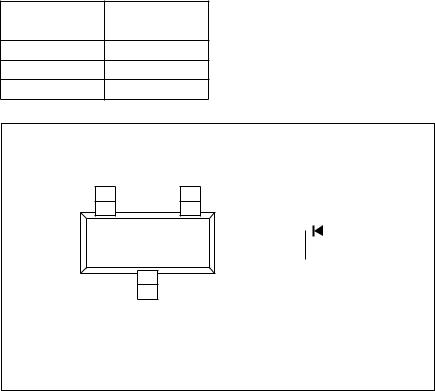
The BAS19, BAS20, BAS21 are general purpose diodes fabricated in planar technology, and encapsulated in small plastic SMD SOT23 packages.
MARKING
TYPE NUMBER
MARKING
CODE
BAS19 JPp
BAS20 JRp
BAS21 JSp
PINNING
PIN |
DESCRIPTION |
|
|
1 |
anode |
|
|
2 |
not connected |
|
|
3 |
cathode |
|
|
handbook, |
2 |
1 |
2 

 1 n.c.
3
3 |
MAM185 |
Fig.1 Simplified outline (SOT23) and symbol.
1996 Apr 16 |
2 |

Philips Semiconductors |
|
|
|
Product specification |
||
|
|
|
|
|
|
|
General purpose diodes |
|
BAS19; BAS20; BAS21 |
||||
|
|
|
|
|
|
|
LIMITING VALUES |
|
|
|
|
|
|
In accordance with the Absolute Maximum Rating System (IEC 134). |
|
|
|
|
||
|
|
|
|
|
|
|
SYMBOL |
PARAMETER |
CONDITIONS |
|
MIN. |
MAX. |
UNIT |
|
|
|
|
|
|
|
VRRM |
repetitive peak reverse voltage |
|
|
|
|
|
|
BAS19 |
|
|
− |
120 |
V |
|
BAS20 |
|
|
− |
200 |
V |
|
BAS21 |
|
|
− |
250 |
V |
|
|
|
|
|
|
|
VR |
continuous reverse voltage |
|
|
|
|
|
|
BAS19 |
|
|
− |
100 |
V |
|
BAS20 |
|
|
− |
150 |
V |
|
BAS21 |
|
|
− |
200 |
V |
|
|
|
|
|
|
|
IF |
continuous forward current |
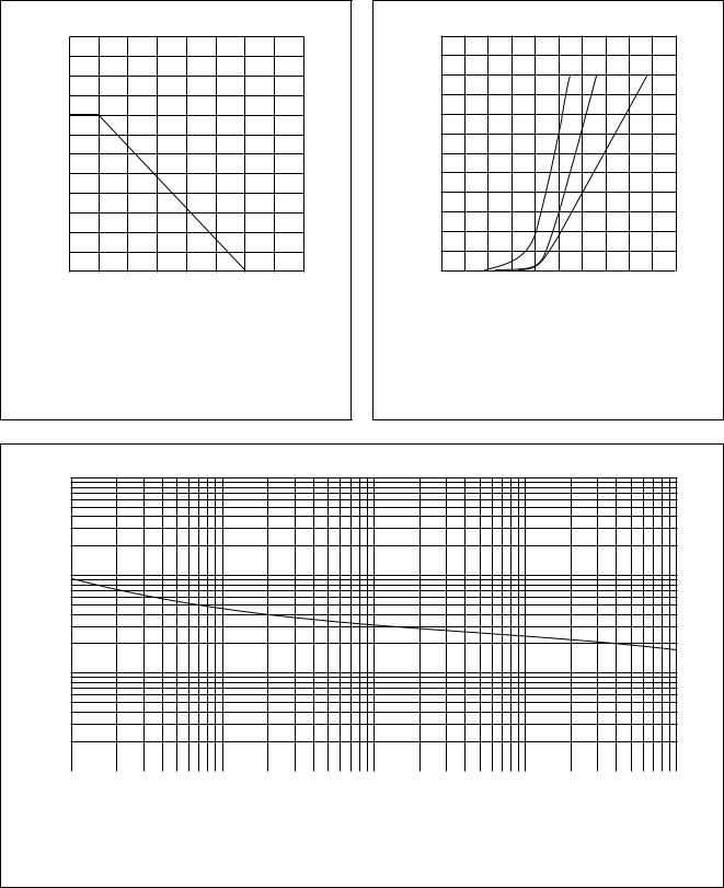
see Fig.2; note 1 |
|
− |
200 |
mA |
IFRM |
repetitive peak forward current |
|
|
− |
625 |
mA |
IFSM |
non-repetitive peak forward current |
square wave; Tj = 25 °C prior to |
|
|
|
|
|
|
surge; see Fig.4 |
|
|
|
|
|
|
t = 1 μs |
|
− |
9 |
A |
|
|
t = 100 μs |
|
− |
3 |
A |
|
|
t = 10 ms |
|
− |
1.7 |
A |
|
|
|
|
|
|
|
Ptot |
total power dissipation |
Tamb = 25 °C; note 1 |
|
− |
250 |
mW |
Tstg |
storage temperature |
|
|
−65 |
+150 |
°C |
Tj |
junction temperature |
|
|
− |
150 |
°C |
Note
1. Device mounted on an FR4 printed-circuit board.
1996 Apr 16 |
3 |

Philips Semiconductors |
|
|
Product specification |
||
|
|
|
|
|
|
General purpose diodes |
BAS19; BAS20; BAS21 |
||||
|
|
|
|
|
|
ELECTRICAL CHARACTERISTICS |
|
|
|
|
|
Tj = 25 °C; unless otherwise specified. |
|
|
|
|
|
|
|
|
|
|
|
SYMBOL |
PARAMETER |
CONDITIONS |
MIN. |
MAX. |
UNIT |
|
|
|
|
|
|
VF |
forward voltage |
see Fig.3 |
|
|
|
|
|
IF = 100 mA |
− |
1.0 |
V |
|
|
IF = 200 mA |
− |
1.25 |
V |
IR |
reverse current |
see Fig.5 |
|
|
|
|
BAS19 |
VR = 100 V |
− |
100 |
nA |
|
|
VR = 100 V; Tj = 150 °C |
− |
100 |
μA |
|
BAS20 |
VR = 150 V |
− |
100 |
nA |
|
|
VR = 150 V; Tj = 150 °C |
− |
100 |
μA |
|
BAS21 |
VR = 200 V |
− |
100 |
nA |
|
|
VR = 200 V; Tj = 150 °C |
− |
100 |
μA |
Cd |
diode capacitance |
f = 1 MHz; VR = 0; see Fig.6 |
− |
5 |
pF |
trr |
reverse recovery time |
when switched from IF = 30 mA to |
− |
50 |
ns |
|
|
IR = 30 mA; RL = 100 Ω; |
|
|
|
|
|
measured at IR = 3 mA; see Fig.8 |
|
|
|
THERMAL CHARACTERISTICS
SYMBOL |
PARAMETER |
|
CONDITIONS |
VALUE |
UNIT |
|
|
|
|
|
|
Rth j-tp |
thermal resistance from junction to tie-point |
|
|
330 |
K/W |
Rth j-a |
thermal resistance from junction to ambient |
note 1 |
|
500 |
K/W |
Note
1. Device mounted on an FR4 printed-circuit board.
1996 Apr 16 |
4 |
Philips Semiconductors |
Product specification |
|
|
General purpose diodes |
BAS19; BAS20; BAS21 |
|
|
GRAPHICAL DATA
MBG442
300 handbook, halfpage
IF (mA)
200
100
0
0 |
100 |
Tamb |
o |
C) |
200 |
|
|
( |
|
Device mounted on an FR4 printed-circuit board.
Fig.2 Maximum permissible continuous forward current as a function of ambient temperature.
MBG384
600 handbook, halfpage
IF (mA)
(1) |
(2) |
(3) |
400
200
0
0 |
1 |
VF |
(V) |
2 |
|
|
|
(1)Tj = 150 °C; typical values.
(2)Tj = 25 °C; typical values.
(3)Tj = 25 °C; maximum values.
Fig.3 Forward current as a function of forward voltage.
MBG703
102 handbook, full pagewidth
IFSM
(A)
10
1
10−1 |
|
|
|
|
|
|
|
|
|
102 |
103 |
|
104 |
||
1 |
10 |
tp (μs) |
|||||
|
|
|
|
|
|
|
|
Based on square wave currents.
Tj = 25 °C prior to surge.
Fig.4 Maximum permissible non-repetitive peak forward current as a function of pulse duration.
1996 Apr 16 |
5 |