Материал: mbrv7030ctlrev0
MOTOROLA
SEMICONDUCTOR TECHNICAL DATA
Order this document by MBRV7030CTL/D
Designer's |
Data Sheet |
|
|
|
|
|
|
|
|
MBRV7030CTL |
|
||||||
SWITCHMODE |
|
|
|
|
|
|
|
|
|
|
|||||||
|
|
|
|
|
|
|
|
|
Motorola Preferred Device |
|
|||||||
|
|
|
|
|
|
|
|
|
|
|
|
||||||
Schottky |
Power |
Rectifier |
|
|
|
|
|
|
|
|
|
|
|
|
|
|
|
|
|
|
|
|
|
|
|
|
|
|
|
|
|
|
|||
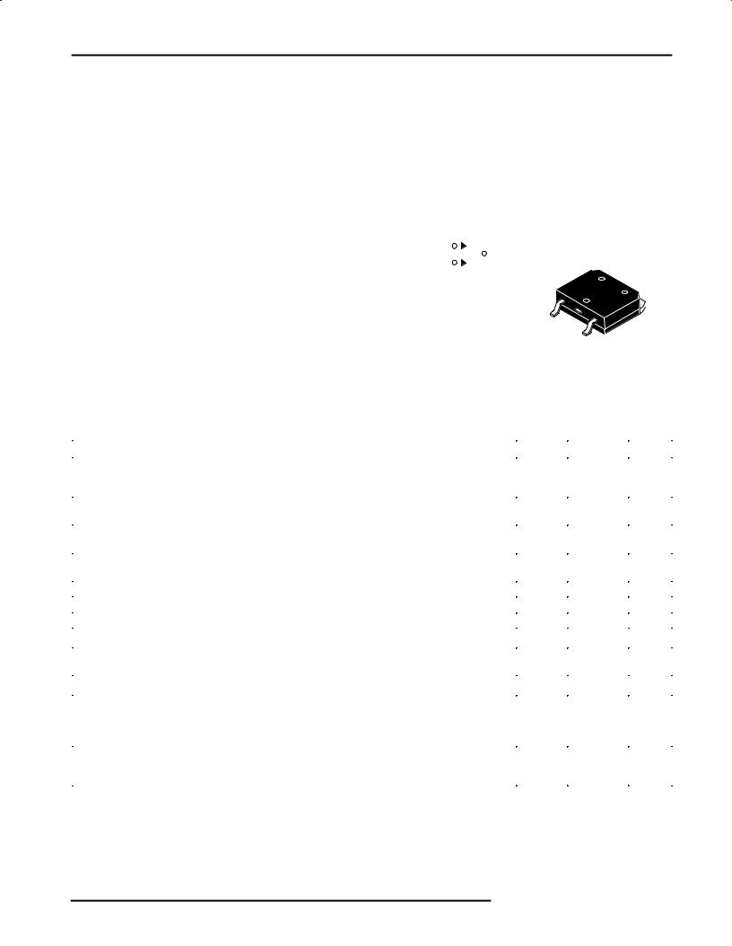
D3PAK Power Surface Mount Package |
|
|
|
|
|
|
|
|
|
|
|
|
|
|
|
||
|
|
|
|
|
|
|
|
SCHOTTKY BARRIER |
|
||||||||
Employing the Schottky Barrier principle in a large area metal±to±silicon power |
|
|
|
||||||||||||||
|
|
|
RECTIFIER |
|
|
|
|
||||||||||
rectifier. Features epitaxial construction with oxide passivation and metal overlay |
|
|
|
70 AMPERES |
|
|
|
|
|||||||||
contact. Ideally suited for low voltage, high frequency switching power supplies; |
|
|
|
|
30 VOLTS |
|
|
|
|
||||||||
free wheeling diodes and polarity protection diodes. |
|
|
|
|
|
|
|
|
|
|
|
|
|
|
|
||
• Compact Package Ideal for Automated Handling |
1 |
|
|
|
|
|
|
|
|
|
|
|
|
|
|
||
• Short Heat Sink Tab Manufactured Ð Not Sheared |
3 |
|
|
|
|
|
2 |
|
|
|
|
|
|
|
|
||
• Highly Stable Oxide Passivated Junction |
|
|
|
|
|
|
|
|
|
|
|
|
|
|
|
||
|
|
|
|
|
|
|
|
|
|
|
|
|
|
|
|
||
• Guardring for Over±voltage Protection |
|
|
|
|
|
|
|
|
|
|
|
|
|
|
|
|
|
• Low Forward Voltage Drop |
|
|
|
|
|
|
|
|
|
|
|
|
|
|
|
|
|
• Monolithic Dual Die Construction. May be Paralleled for High Current Output. |
|
|
|
|
|
|
|
|
|
||||||||
|
|
|
|
|
|
|
|
|
|||||||||
|
|
|
|
|
|
|
|
|
|||||||||
Mechanical Characteristics: |
|
|
|
|
|
|
|
|
|
1 |
|
|
2 |
|
|||
• Case: Epoxy, Molded |
|
|
|
|
|
|
|
|
|
|
|
|
|
||||
|
|
|
|
|
|
|
|
|
|
|
|
|
|
|
|||
|
|
|
|
|
|
|
|
|
|
|
|
|
|
|
|
|
|
• Weight: 2 Grams (approximately) |
|
|
|
|
|
|
|
|
|
|
3 |
|
|
|
|
||
• Finish: All External Surfaces Corrosion Resistant and Terminal Leads are |
|
|
|
|
|
|
|
|
|
||||||||
Readily Solderable |
|
|
|
|
|
|
|
|
|
|
CASE 433A±01, Style 1 |
|
|||||
• Maximum Temperature of 260°C for 10 Seconds for Soldering |
|
|
|
|
|
|
|
|
|
||||||||
|
|
|
|
|
|
|
|
|
|
D3PAK |
|
|
|
|
|||
• Shipped 29 Units per Plastic Tube |
|
|
|
|
|
|
|
|
|
|
|
|
|
|
|
||
|
|
|
|
|
|
|
|
|
|
|
|
|
|
|
|
||
• Marking: MBRV7030CTL |
|
|
|
|
|
|
|
|
|
|
|
|
|
|
|
|
|
|
|
|
|
|
|
|
|
|
|
|
|
|
|
|
|
||
MAXIMUM RATINGS |
|
|
|
|
|
|
|
|
|
|
|
|
|
|
|
|
|
|
|
|
|
|
|
|
|
|
|
|
|
|
|
|
|
|
|
|
Rating |
|
|
|
|
|
|
|
|
Symbol |
|
Value |
Unit |
||||
|
|
|
|
|
|
|
|
|
|
|
|
|
|
|
|
|
|
Peak Repetitive Reverse Voltage |
|
|
|
|
|
|
|
|
|
VRRM |
|
30 |
|
|
V |
||
Working Peak Reverse Voltage |
|
|
|
|
|
|
|
|
|
VRWM |
|
|
|
|
|
|
|
DC Blocking Voltage |
|
|
|
|
|
|
|
|
|
|
VR |
|
|
|
|
|
|
Average Rectified Forward Current |
|
Per Leg |
|
|
IO |
|
35 |
|
|
A |
|||||||
(At Rated VR, TC = 135°C) |
|
Per Package |
|
|
|
|
70 |
|
|
|
|
||||||
Peak Repetitive Forward Current |
|
Per Leg |
|
|
IFRM |
|
70 |
|
|
A |
|||||||
(At Rated VR, Square Wave, 20 kHz, TC = 135°C) |
|
|
|
|
|
|
|
|
|
|
|
|
|
|
|
||
Non±Repetitive Peak Surge Current |
|
Per Package |
|
|
IFSM |
|
500 |
|
|
A |
|||||||
(Surge applied at rated load conditions, halfwave, single phase, 60 Hz) |
|
|
|
|
|
|
|
|
|
|
|
|
|
|
|
||
|
|
|
|
|
|
|
|
|
|
|
|
|
|
|
|
|
|
Storage / Operating Case Temperature |
|
|
|
|
|
|
|
|
|
Tstg, TC |
|
± 55 to 150 |
|
°C |
|||
Operating Junction Temperature |
|
|
|
|
|
|
|
|
|
TJ |
|
± 55 to 150 |
|
°C |
|||
Voltage Rate of Change (Rated VR, TJ = 25°C) |
|
|
|
|
|
|
|
|
|
dv/dt |
|
10,000 |
V/ms |
||||
THERMAL CHARACTERISTICS |
|
|
|
|
|
|
|
|
|
|
|
|
|
|
|
|
|
|
|
|
|
|
|
|
|
|
|
|
|
|
|
|
|
||
Thermal Resistance Ð Junction±to±Case |
|
Per Leg |
|
|
RqJC |
|
0.59 |
°C/W |
|||||||||
Thermal Resistance Ð Junction±to±Ambient (2) |
|
Per Leg |
|
|
RqJA |
|
54 |
|
|
|
|
||||||
ELECTRICAL CHARACTERISTICS |
|
|
|
|
|
|
|
|
|
|
|
|
|
|
|
|
|
|
|
|
|
|
|
|
|
|
|
|
|
|
|
|
|
||
Maximum Instantaneous Forward Voltage (1), see Figure 2 |
Per Leg |
|
|
VF |
|
|
|
|
V |
||||||||
(IF = 35 A, TJ = 25°C) |
|
|
|
|
|
|
|
|
|
|
|
|
0.50 |
|
|
|
|
(IF = 70 A, TJ = 25°C) |
|
|
|
|
|
|
|
|
|
|
|
|
0.62 |
|
|
|
|
(IF = 35 A, TJ = 100°C) |
|
|
|
|
|
|
|
|
|
|
|
|
0.47 |
|
|
|
|
Maximum Instantaneous Reverse Current, see Figure 4 |
Per Leg |
|
|
IR |
|
|
|
mA |
|||||||||
(Rated VR, TJ = 25°C) |
|
|
|
|
|
|
|
|
|
|
|
|
2.0 |
|
|
|
|
(Rated VR, TJ = 100°C) |
|
|
|
|
|
|
|
|
|
|
|
|
40 |
|
|
|
|
(1)Pulse Test: Pulse Width ≤ 250 μs, Duty Cycle ≤ 2%
(2)Rating applies when using minimum pad size, FR4 PC Board
Designer's Data for ªWorst Caseº Conditions Ð The Designer's Data Sheet permits the design of most circuits entirely from the information presented. SOA Limit curves Ð representing boundaries on device characteristics Ð are given to facilitate ªworst caseº design.
Designer's and Switchmode are trademarks of Motorola, Inc.
Preferred devices are Motorola recommended choices for future use and best overall value.
Motorola,IncTMOS. 1997 Power MOSFET Transistor Device Data
MBRV7030CTL
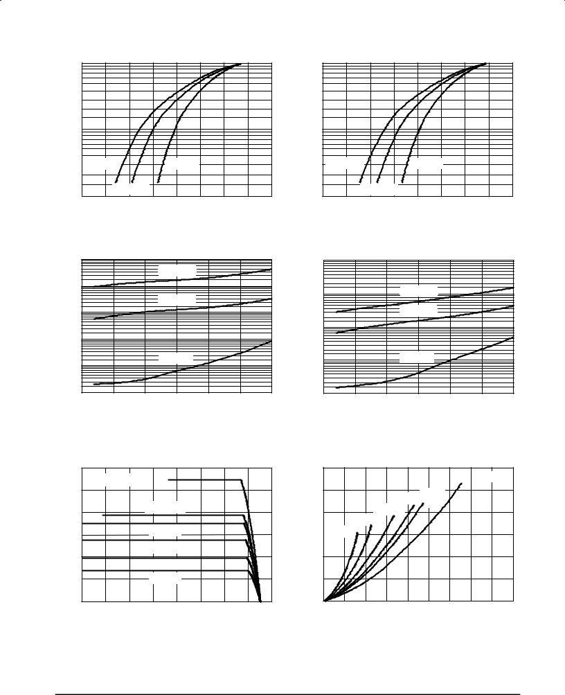
TYPICAL ELECTRICAL CHARACTERISTICS
I F , INSTANTANEOUS FORWARD CURRENT (AMPS)
100
10
TJ = 150°C |
TJ = 25°C |
1.0TJ = 100°C
0 |
0.2 |
0.4 |
0.6 |
0.8 |
|
VF, INSTANTANEOUS FORWARD VOLTAGE (VOLTS) |
|
||
Figure 1. Typical Forward Voltage
CURRENT (AMPS) |
100 |
|
|
|
|
|
|
|
|
|
|
FORWARD |
10 |
|
|
|
|
INSTANTANEOUS |
1.0 |
TJ = 100°C |
TJ = 25°C |
|
|
|
TJ = 150°C |
|
|
|
|
F |
0 |
0.2 |
0.4 |
0.6 |
0.8 |
, |
|
|
|
|
|
I |
VF, MAXIMUM INSTANTANEOUS FORWARD VOLTAGE (VOLTS) |
|
|||
|
|
||||
Figure 2. Maximum Forward Voltage
(AMPS) |
1.0 |
|
|
|
|
|
TJ = 150°C |
|
|
CURRENT |
0.1 |
|
|
|
|
|
TJ = 100°C |
|
|
0.01 |
|
|
|
|
REVERSE |
|
|
|
|
0.001 |
|
|
|
|
, |
|
|
|
|
R |
|
|
|
|
I |
|
|
TJ = 25°C |
|
0.0001 |
|
|
||
|
|
|
||
0.00001 |
10 |
20 |
30 |
|
|
0 |
|||
|
|
VR, REVERSE VOLTAGE (VOLTS) |
|
|
(AMPS) |
10 |
|
|
|
|
|
|
|
|
CURRENT |
1.0 |
|
TJ = 150°C |
|
|
|
TJ = 100°C |
|
|
REVERSE |
|
|
|
|
0.1 |
|
|
|
|
|
|
|
|
|
, MAXIMUM |
0.01 |
|
TJ = 25°C |
|
|
|
|
|
|
R |
|
|
|
|
I |
|
|
|
|
|
0.001 0 |
10 |
20 |
30 |
|
|
VR, REVERSE VOLTAGE (VOLTS) |
|
|
Figure 3. Typical Reverse Current |
Figure 4. Maximum Reverse Current |
(AMPS)CURRENTFORWARDAVERAGE |
60 |
|
|
|
|
|
|
|
|
(WATTS)DISSIPATIONPOWERAVERAGE, |
30 |
|
dc |
TJ = 150°C |
|
|
|
|
|
|
|
|
|
|
|
||||
|
|
FREQ = 20 kHz |
|
dc |
|
|
|
|
|
|
|
|||
|
50 |
|
|
|
|
|
|
|
|
|
25 |
Ipk/Io = p |
square |
|
|
|
|
|
|
|
|
|
|
|
|
|
|
||
|
|
|
|
square wave |
|
|
|
|
|
|
wave |
|
||
|
40 |
|
|
|
|
|
|
|
20 |
Ipk/Io = 5 |
|
|
||
|
|
|
|
|
|
|
|
|
|
|
|
|||
|
|
|
|
|
|
|
|
|
|
Ipk/Io = 10 |
|
|
||
|
|
|
|
|
|
|
|
|
|
|
|
|
|
|
|
30 |
|
|
Ipk/Io = p |
|
|
|
|
|
15 |
Ipk/Io = 20 |
|
|
|
|
|
|
|
|
|
|
|
|
|
|
|
|||
|
|
|
|
Ipk/Io = 5 |
|
|
|
|
|
|
|
|
|
|
|
20 |
|
|
Ipk/Io = 10 |
|
|
|
|
|
10 |
|
|
|
|
|
|
|
|
|
|
|
|
|
|
|
|
|
||
O |
10 |
|
|
Ipk/Io = 20 |
|
|
|
|
FO |
5 |
|
|
|
|
|
|
|
|
|
|
|
|
|
|
|
|
|
||
, |
|
|
|
|
|
|
|
|
|
|
|
|
|
|
I |
0 |
|
|
|
|
|
|
|
|
P |
0 |
|
|
|
|
20 |
40 |
60 |
80 |
100 |
120 |
140 |
160 |
|
25 |
50 |
75 |
||
|
0 |
|
0 |
|||||||||||
|
|
|
TC, CASE TEMPERATURE (°C) |
|
|
|
|
IO, AVERAGE FORWARD CURRENT (AMPS) |
||||||
Figure 5. Current Derating (Per Leg) |
Figure 6. Forward Power Dissipation (Per Leg) |
2 |
Motorola TMOS Power MOSFET Transistor Device Data |
MBRV7030CTL
TYPICAL ELECTRICAL CHARACTERISTICS
C, CAPACITANCE (pF)
100,000
TJ = 25°C
10,000
1,000 |
|
|
1.0 |
10 |
100 |
VR, REVERSE VOLTAGE (VOLTS)
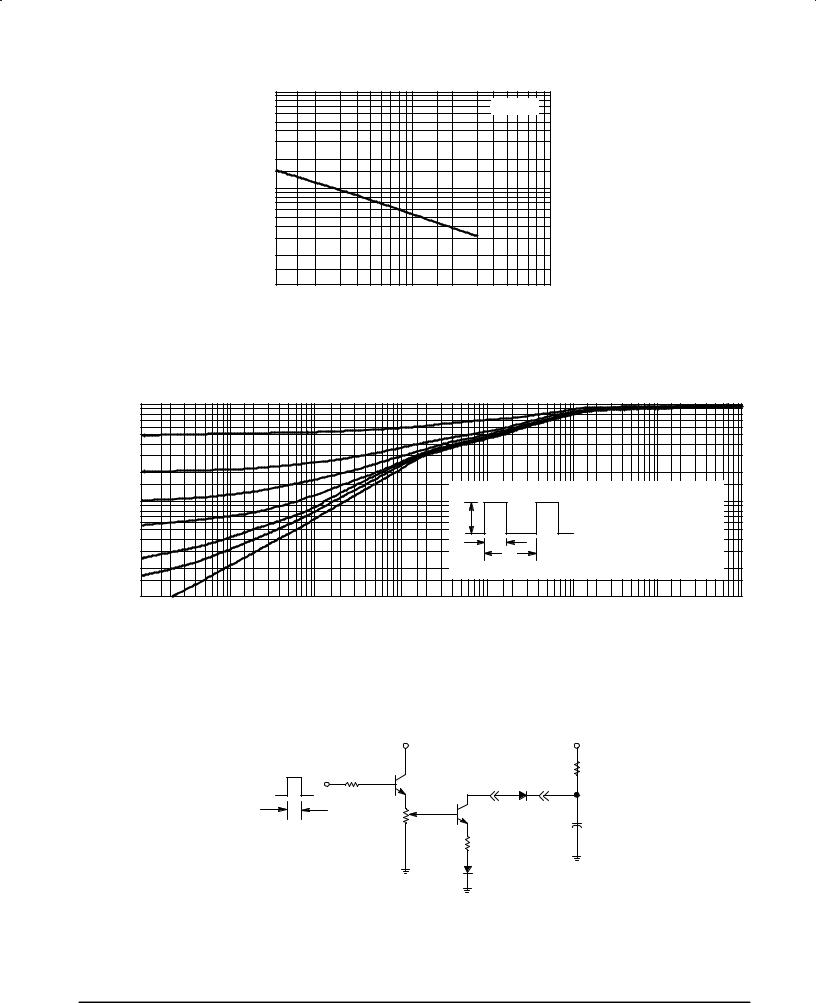
Figure 7. Capacitance
SAFE OPERATING AREA
|
1.0 |
|
|
|
|
|
|
|
|
0.1 |
|
|
|
P(pk) |
|
RθJC(t) = r(t) RθJC |
|
NORMALIZEDr(t),EFFECTIVE |
TRANSIENTRESISTANCETHERMAL |
|
|
|
|
|
D CURVES APPLY FOR POWER |
|
|
|
|
t1 |
|
PULSE TRAIN SHOWN |
|
||
|
|
|
|
READ TIME AT t |
|
|||
|
|
|
t2 |
|
1 |
|
||
|
|
|
|
TJ(pk) ± TC = P(pk) RθJC(t) |
|
|||
|
|
|
DUTY CYCLE, D = t1/t2 |
|
|
|
||
|
0.01 |
|
|
|
|
|
|
|
|
0.000001 |
0.00001 |
0.0001 |
0.001 |
0.01 |
0.1 |
1.0 |
10 |
t, TIME (SECONDS)
Figure 8. Thermal Response
|
VCC |
|
+ 150 V, |
|
|
12 Vdc |
|
10 mAdc |
|
12 V |
100 |
|
|
2 kW |
2N2222 |
D.U.T. |
|
||
|
|
|
||
2 ms |
CURRENT |
|
2N6277 |
|
1 kHz |
|
+ |
||
|
AMPLITUDE |
100 W |
|
4 mF |
|
ADJUST |
CARBON |
1 CARBON |
|
|
0 ±10 AMPS |
|
|
|
|
|
|
|
|
|
|
|
1N5817 |
|
Figure 9. Test Circuit for Repetitive
Reverse Current
Motorola TMOS Power MOSFET Transistor Device Data |
3 |
MBRV7030CTL
INFORMATION FOR USING THE DPAK SURFACE MOUNT PACKAGE
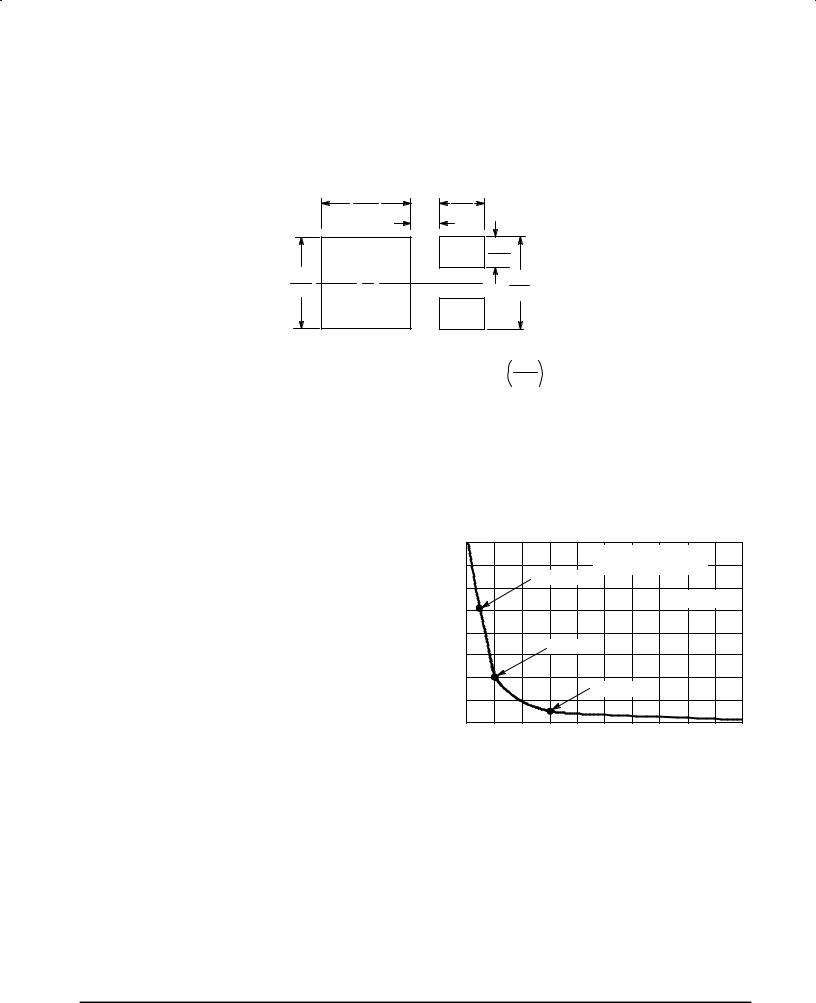
RECOMMENDED FOOTPRINT FOR SURFACE MOUNTED APPLICATIONS
Surface mount board layout is a critical portion of the total design. The footprint for the semiconductor packages must be the correct size to ensure proper solder connection interface
between the board and the package. With the correct pad geometry, the packages will self align when subjected to a solder reflow process.
0.165 |
|
0.118 |
4.191 |
0.100 |
3.0 |
|
|
|
|
2.54 |
|
|
|
0.063 |
|
|
1.6 |
0.190 |
|
0.243 |
4.826 |
|
6.172 |
inches
mm
POWER DISSIPATION FOR A SURFACE MOUNT DEVICE
The power dissipation for a surface mount device is a function of the drain pad size. These can vary from the minimum pad size for soldering to a pad size given for maximum power dissipation. Power dissipation for a surface
mount device is determined by TJ(max), the maximum rated junction temperature of the die, RθJA, the thermal resistance
from the device junction to ambient, and the operating temperature, TA. Using the values provided on the data sheet, PD can be calculated as follows:
PD = |
TJ(max) ± TA |
|
RθJA |
||
|
The values for the equation are found in the maximum ratings table on the data sheet. Substituting these values into the equation for an ambient temperature TA of 25°C, one can calculate the power dissipation of the device. For a D3PAK device, PD is calculated as follows.
PD = 150°C ± 25°C = 2.31 Watts
54°C/W
The 54°C/W for the D3PAK package assumes the use of the recommended footprint on a glass epoxy printed circuit board to achieve a power dissipation of 2.31 Watts. There are other alternatives to achieving higher power dissipation from the surface mount packages. One is to increase the area of the drain pad. By increasing the area of the drain pad, the power
dissipation can be increased. Although one can almost double the power dissipation with this method, one will be giving up area on the printed circuit board which can defeat the purpose of using surface mount technology. For example, a graph of RθJA versus drain pad area is shown in Figure 11.
JUNCTION |
100 |
|
|
Board Material = 0.0625″ |
|
||
|
|
|
|
|
|||
|
|
|
1.75 Watts |
G±10/FR±4, 2 oz Copper |
|
||
|
80 |
|
|
|
|
||
|
|
|
|
|
|
||
THERMAL RESISTANCE, |
TO AMBIENT (°C/W) |
|
|
|
TA = 25°C |
|
|
|
|
|
|
|
|||
60 |
|
|
|
|
|
||
|
|
3.0 Watts |
|
|
|
||
40 |
|
|
5.0 Watts |
|
|
||
|
|
|
|
|
|||
, |
|
|
|
|
|
|
|
θJA |
|
|
|
|
|
|
|
R |
|
200 |
|
|
|
|
|
|
|
2 |
4 |
6 |
8 |
10 |
|
|
|
|
|
A, AREA (SQUARE INCHES) |
|
|
|
Figure 10. Thermal Resistance versus Drain Pad Area for the D3PAK Package (Typical)
Another alternative would be to use a ceramic substrate or an aluminum core board such as Thermal Clad . Using a board material such as Thermal Clad, an aluminum core board, the power dissipation can be doubled using the same footprint.
4 |
Motorola TMOS Power MOSFET Transistor Device Data |

MBRV7030CTL
SOLDER STENCIL GUIDELINES
Prior to placing surface mount components onto a printed circuit board, solder paste must be applied to the pads. Solder stencils are used to screen the optimum amount. These stencils are typically 0.008 inches thick and may be made of brass or stainless steel. For packages such as the SC±59, SC±70/SOT±323, SOD±123, SOT±23, SOT±143, SOT±223, SO±8, SO±14, SO±16, and SMB/SMC diode packages, the stencil opening should be the same as the pad size or a 1:1 registration. This is not the case with the DPAK and D2PAK packages. If one uses a 1:1 opening to screen solder onto the drain pad, misalignment and/or ªtombstoningº may occur due to an excess of solder. For these two packages, the opening in the stencil for the paste should be approximately 50% of the tab area. The opening for the leads is still a 1:1 registration. Figure 12 shows a typical stencil for the DPAK and D2PAK packages. The pattern of the opening in the stencil for the drain pad is not critical as long as it allows approximately 50% of the pad to be covered with paste.
SOLDER PASTE
OPENINGS
STENCIL
Figure 11. Typical Stencil for DPAK and D2PAK Packages
SOLDERING PRECAUTIONS
The melting temperature of solder is higher than the rated temperature of the device. When the entire device is heated to a high temperature, failure to complete soldering within a short time could result in device failure. Therefore, the following items should always be observed in order to minimize the thermal stress to which the devices are subjected.
•Always preheat the device.
•The delta temperature between the preheat and soldering should be 100°C or less.*
•When preheating and soldering, the temperature of the leads and the case must not exceed the maximum temperature ratings as shown on the data sheet. When
using infrared heating with the reflow soldering method, the difference shall be a maximum of 10°C.
•The soldering temperature and time shall not exceed 260°C for more than 10 seconds.
•When shifting from preheating to soldering, the maximum temperature gradient shall be 5°C or less.
•After soldering has been completed, the device should be allowed to cool naturally for at least three minutes. Gradual cooling should be used as the use of forced cooling will increase the temperature gradient and result in latent failure due to mechanical stress.
•Mechanical stress or shock should not be applied during cooling.
*Soldering a device without preheating can cause excessive thermal shock and stress which can result in damage to the device.
*Due to shadowing and the inability to set the wave height to incorporate other surface mount components, the D2PAK is not recommended for wave soldering.
Motorola TMOS Power MOSFET Transistor Device Data |
5 |