Материал: 2
|
20 |
|
|
|
|
|
(ns) |
|
|
|
|
VCC = 5 V |
(ns) |
16 |
|
|
|
TA = 25°C |
||
DELAY |
|
|
|
LS00 |
DELAY |
|
|
|
|
|
|||
12 |
|
|
|
|
||
PROPAGATION, |
|
|
|
|
PROPAGATION, |
|
|
|
|
tPLH |
|
||
|
|
|
|
|
|
|
|
8 |
|
|
tPHL |
|
|
PD |
4 |
|
|
|
|
PD |
t |
|
|
|
|
t |
|
|
0 |
20 |
40 |
60 |
80 |
100 |
|
|
|
CL, LOAD CAPACITANCE (pF) |
|
|
|
|
|
|
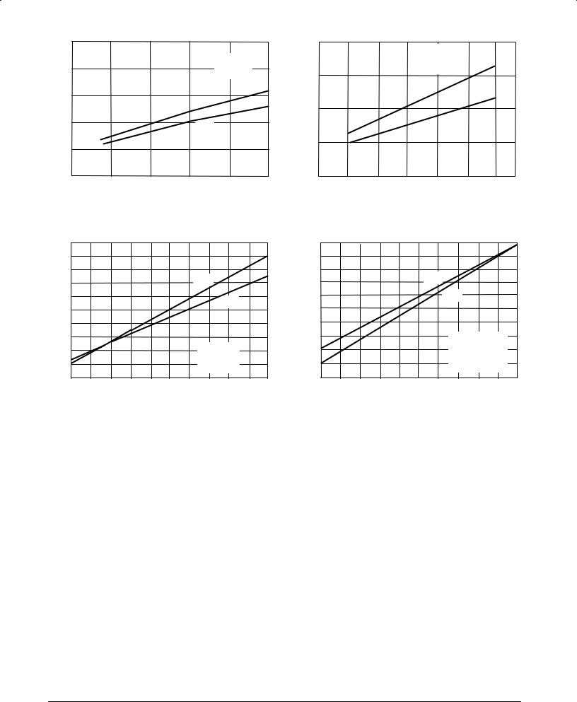
Figure 2-11a* |
|
|
|
|
20 |
|
|
|
|
|
(ns) |
|
|
|
|
|
(ns) |
DELAY |
|
|
|
tPLH |
|
DELAY |
PROPAGATION, |
10 |
|
|
|
tPHL |
PROPAGATION, |
|
|
|
|
|
||
|
|
|
|
|
|
|
PD |
|
|
|
V |
= 5 V |
PD |
t |
|
|
|
CC |
|
t |
|
|
|
|
TA = 25°C |
|
|
|
|
|
|
F240 |
|
|
|
0 |
|
|
500 |
|
1000 |
|
0 |
|
|
|
||
12
VCC = 5 V
TA = 25°C
F00
9
tPLH
6
tPHL
3
50 |
100 |
150 |
200 |
250 |
300 |
CL, LOAD CAPACITANCE (pF)
Figure 2-11b*
20
tPLH
tPHL
10
VCC = 5 V
TA = 25°C
F240
All Outputs Driven
0
0 |
500 |
1000 |
CL, LOAD CAPACITANCE (pF) |
CL, LOAD CAPACITANCE (pF) |
Figure 2-11c* |
Figure 2-11d* |
*Data for Figures 2-11a through 2-11c was taken with only one output switching at a time. Figure 2-11d data was taken with all 8 inputs of the F240 tied together.
LS/FAST ESD CHARACTERISTICS. Electrostatic Discharge (ESD) sensitivity for Motorola TTL is characterized using several methodologies (HBM, MM, CDM). It is extremely important to understand that ESD sensitivity values alone are not sufficient when comparing devices. In an attempt to reduce correlation problems between various pieces of test equipment, all of which meet Mil-Std-883C requirements, tester specific information as well as actual device ESD hardness levels are given in controlled documents and are available upon request. The continuing improvements of ESD sensitivity through redesigns of Motorola TTL has resulted in minimum ESD levels for all new products and redesigns of >4000 volts for FAST and >3500 volts for LS. For device specific values reference the following specifications:
LS: 12MRM 93831A
FAST: 12MRM 93830A
FAST AND LS TTL DATA
2-6