Материал: 41_price2004

Anal. Chem. 2004, 76, 4849-4855
Deformation-Induced Release of ATP from Erythrocytes in a Poly(dimethylsiloxane)-Based Microchip with Channels That Mimic Resistance Vessels
Alexander K. Price, David J. Fischer, R. Scott Martin, and Dana M. Spence*,†
Department of Chemistry, Saint Louis University, St. Louis, Missouri 63103
The ability of nitric oxide to relax smooth muscle cells surrounding resistance vessels in vivo is well documented. Here, we describe a series of studies designed to quantify amounts of adenosine triphosphate (ATP), a known stimulus of NO production in endothelial cells, released from erythrocytes that are mechanically deformed as these cells traverse microbore channels in lithographically patterned microchips. Results indicate that micromolar amounts of ATP are released from erythrocytes flowing through channels having cross sectional dimensions of 60 38 ím (2.22 ( 0.50 íM ATP).
»icroscopic images indicate that erythrocytes, when being pumped through the microchip channels, migrate toward the center of the channels, leaving a cell-free or skimming layer at the walls of the channel, a profile known to exist in circulatory vessels in vivo. A comparison of the amounts of ATP released from RBCs mechanically deformed in microbore tubing (2.54 ( 0.15 íM) vs a microchip (2.59 ( 0.32 íM) suggests that channels in microchips may serve as functional biomimics of the microvasculature. Control studies involving diamide, a membrane-stiffening agent, suggest that the RBC-derived ATP is not due to cell lysis but rather physical deformation.
Red blood cells (RBCs) are well known for their ability to transport oxygen in vivo. In addition to oxygen transport, RBCs have also been reported to serve as oxygen sensors.1 That is, when subjected to low levels of oxygen (hypoxia), RBCs have been shown to release micromolar amounts of adenosine triphosphate (ATP), a known stimulus of endothelium-derived nitric oxide.2 This NO induces the production of guanalyl cyclase-catalyzed cyclic guanosine monophosphate, which, in turn, relaxes the smooth muscle cells surrounding circulatory vessels, thereby increasing RBC flow and oxygen delivery to the hypoxic tissue. In addition to hypoxia-induced ATP release from RBCs, there exist other modes, both pharmacological and physiological, of inducing ATP release from intact RBCs. For example, pharmacologically, the addition of iloprost,3 forskolin, or Sp-cAMP (a cyclic adenosine
* Corresponding author. E-mail: dspence@chem.wayne.edu.
† Current address: Department of Chemistry, Wayne State University, Detroit, MI 48202.
(1)Ellsworth, M. L. Acta Physiol. Scand. 2000, 168, 551-559.
(2)Bergfeld, G. R.; Forrester, T. Cardiovasc. Res. 1992, 26, 40-47.
10.1021/ac0495992 CCC: $27.50 © 2004 American Chemical Society Published on Web 07/16/2004
monophosphate analogue) will induce ATP release from RBCs.4 Physiologically, mechanical deformation of RBCs has been reported to stimulate the release of ATP from these cells.4-6 In vivo, RBCs undergo deformation as they traverse resistance vessels such as arterioles and capillaries having inside diameters of 25-100 and 10-25 ím, respectively. The mechanical stress placed upon RBCs in vivo has been modeled by forcing these cells through filter paper having pores with inside diameters of 12, 8, and 5 ím.4,5 Filtration of RBCs through such micropores has been reported to approximate the forces applied to the RBC as it traverses capillaries.7,8
Although the filtration approach helps in understanding the mechanism with which RBCs pass through the microcirculation, RBCs are also deformed in larger vessels, i.e., arterioles having diameters between 25 and 100 ím, which are major determinants of vascular resistance in vivo. Indeed, it was reported that the passage of RBCs through rat cerebral penetrating arterioles with passive internal diameters of 60 ím resulted in significant release of ATP.9 Recently, we have developed an alternative method for studying ATP release from RBCs that permits the determination of ATP release from RBCs as they traverse fused-silica microbore tubing10,11 with internal diameters comparable to those of resistance vessels in the intact circulation.12,13 In contrast to filtration through micropores, this system permits ATP release to be determined on-line and in real time in a continuous flow stream.
(3)Olearczyk, J. J.; Stephenson, A. H.; Lonigro, A. J.; Sprague, R. S. Med. Sci. Monit. 2001, 7, 669-674.
(4)Sprague, R. S.; Ellsworth, M. L.; Stephenson, A. H.; Kleinhenz, M. E.; Lonigro, A. J. Am. J. Physiol. 1998, 275, H1726-H1732.
(5)Sprague, R. S.; Ellsworth, M. L.; Stephenson, A. H.; Lonigro, A. J. Am. J. Physiol. 1996, 271, H2717-H2722.
(6)Sprague, R. S.; Ellsworth, M. L.; Stephenson, A. H.; Lonigro, A. J. Exp. Clin. Cardiol. 1998, 3, 73-77.
(7)Secomb, T. W.; Hsu, R. J. Biochem. Eng. 1996, 118, 538-544.
(8)Secomb, T. W.; Hsu, R. Biophys. J. 1996, 71, 1095-1101.
(9)Dietrich, H. H.; Ellsworth, M. L.; Sprague, R. S.; Dacey Jr., R. G. Am. J. Physiol. 2000, 278, H1294-H1298.
(10)Sprung, R. J.; Sprague, R. S.; Spence, D. M. Anal. Chem. 2002, 74, 2274- 2278.
(11)Edwards, J. L.; Sprung, R. J.; Sprague, R. S.; Spence, D. M. Analyst 2001, 126, 1257-1260.
(12)Goldsmith, H. L.; Mason, S. G. In Theoretical and Clinical Hemorheology; Hartert, H. H., Copley, A. L., Eds.; Springer-Vertad.: Berlin, 1971; pp 47- 59.
(13)Goldsmith, H. L. J. Gen. Physiol. 1968, 52, 5s-28s.
Analytical Chemistry, Vol. 76, No. 16, August 15, 2004 4849

Although it has been demonstrated that microbore tubing is able to serve as a mimic of resistance vessels by mechanically deforming RBCs, this approach does have limitations. Due to the complexity of arteriole and capillary vessel networks in the pulmonary circulation, constructing a physiological mimic would be difficult because of the following: (1) the number of connectors and pieces of tubing required to construct such a system, (2) real vessels in vivo are as small as 1 mm in length14 and connecting such lengths of fused-silica microbore tubing with standard fittings is nearly impossible, and (3) vessels in vivo, when reducing from arteries to arterioles to capillaries, scale uniformly.15 Although tubing of different inside diameters can be employed to mime this reduction, it is difficult to scale the tubing identical to that seen in vivo. However, scaling down of channel dimensions may be possible with basic microchip fabrication technology.16,17 Therefore, fabricated microchips having channels whose dimensions approximate those of resistance vessels may be a viable model of resistance vessels for studying the release of ATP from RBCs subjected to mechanical deformation. Since their initial description in 1990,18 microchips have been used to perform complex separations, immunoassays, DNA analysis, and clinical diagnostics.17,19 Sample streams can be moved throughout the chip by either electrophoretic or hydrodynamic pumping.16,20,21 Detecting the analytes directly in the micrometer-sized channels can be accomplished by a variety of mechanisms including laser-induced fluorescence, electrochemical, or refractive index detection.22
While these devices can be made in a variety of substrates, devices fabricated in poly(dimethylsiloxane) (PDMS) hold several unique advantages. Soft lithography methods (molding of prepolymer against a lithographically defined master) can be used to fabricate devices in laboratories with limited cleanroom capabilities.23,24 Rapid prototyping procedures, where inexpensive films are used as masks, can be utilized to make the initial master, greatly reducing the costs associated with making new designs. This same master can be used to make many devices, and the resulting PDMS slab can be reversibly or irreversibly (through the use of a plasma cleaner) sealed to itself or other substrates such as glass.23,24 In addition to the applications mentioned above, it has been shown that PDMS-based devices can be used to pattern25-27 and manipulate cells.28-33 However, while various cell lines have been investigated in PDMS-based microchips, manipu-
(14)Dietrich, H. H.; Kajita, Y.; Dacey Jr., R. G. Am. J. Physiol. 1996, 271, H1109- H1116.
(15)Enderle, J.; Blanchard, S.; Bronzino, J. Introduction to Biomedical Engineering; Academic Press: San Diego, 2000.
(16)Reyes, D. R.; Iossifidis, D.; Auroux, P. A.; Manz, A. Anal. Chem. 2002, 74, 2623-2636.
(17)Auroux, P. A.; Iossifidis, D.; Reyes, D. R.; Manz, A. Anal. Chem. 2002, 74, 2637-2652.
(18)Manz, A.; Graber, N.; Widmer, H. M. Sens. Actuators, B 1990, 1, 244-248.
(19)Gawron, A. J.; Martin, R. S.; Lunte, S. M. Eur. J. Pharm. Sci. 2001, 14, 1-12.
(20)Polson, N. A.; Hayes, M. A. Anal. Chem. 2001, 73, 312A-319A.
(21)Seller, K.; Fan, Z. H.; Fluri, K.; Harrision, D. J. Anal. Chem. 1994, 66, 3485- 3491.
(22)Schwarz, M. A.; Hauser, P. C. Lab Chip 2001, 1, 1-6.
(23)McDonald, J. C.; Duffy, D. C.; Anderson, J. R.; Chiu, D. T.; Wu, H.; Schueller, O. J. A.; Whitesides, G. M. Electrophoresis 2000, 21, 27-40.
(24)McDonald, J. C.; Whitesides, G. M. Acc. Chem. Res. 2002, 35, 491-499.
(25)Mata, A.; Boehm, C.; Fleischman, A. J.; Muschler, G.; Roy, S. Biomed. Microdevices 2002, 4, 267-275.
(26)Takayama, S.; McDonald, J. C.; Ostuni, E.; Liang, M. N.; Kenis, P. J. A.; Ismagilov, R. F.; Whitesides, G. M. Proc. Natl. Acad. Sci. U.S.A. 1999, 96, 5545-5548.
lation of RBCs in a microchip has been limited to immunoseparations 34 and investigating the effect of the malaria virus on cell rigidity.35
Here, we report the on-chip determination of ATP release derived from mechanically deformed RBCs. The erythrocytes are deformed while passing through channels, via hydrodynamic pumping, in a microchip fabricated from PDMS. An important aspect of this work is that the ATP is determined on-chip and in real time without any cell lysis or agonist. Rather, while traversing the fabricated channels, the ATP release is due to a physical stress placed upon the RBCs that is similar to the physical stress that these cells would be subjected to in resistance vessels in vivo. In this respect, the channels in the fabricated microchip actually serve as biomimetic resistance vessels.
EXPERIMENTAL SECTION
Chemiluminescent Determination of ATP. ATP (in both standards and that released from RBCs) was determined using the luciferin/luciferase reaction.10 The light intensity of the chemiluminescence produced from this reaction is proportional to the amount of ATP present. Firefly tail extract was used as the source for luciferase (FLE-50, Sigma, St. Louis, MO). In all studies, 2 mg of D-luciferin (L 9504, Sigma) was added to each vial of the firefly tails to enhance the sensitivity of the reaction. The luciferin/ luciferase solution was then prepared by diluting the luciferin/ luciferase mixture in 5 mL of distilled, deionized 18 M¿ water (DDW). All dilutions of standard ATP and RBCs were made with a buffered physiological salt solution (PSS (in mM): 4.7 KCl, 2.0 CaCl2, 1.2 MgSO4, 140.5 NaCl, 21.0 tris(hydroxymethyl)aminomethane, and 11.1 dextrose with 5% bovine serum albumin, pH adjusted to 7.4). The luciferin/luciferase mixture was always prepared on the day of use.
Generation of Washed Red Blood Cells. RBCs were prepared on the day of use. For obtaining rabbit RBCs, male New Zealand White rabbits (2.0-2.5 kg) were anesthetized with ketamine (8.0 mg/kg) and xylazine (1.0 mg/kg) followed by pentobarbital sodium (15 mg/kg iv). After tracheotomy, the rabbits were mechanically ventilated (tidal volume 20 mL/kg, rate 20 breaths/min; Harvard ventilator). A catheter was placed into a carotid artery, heparin (500 units, iv) was administered, and after 10 min, animals were exsanguinated. Blood was collected into vials, and the RBCs were separated from other formed elements and plasma by centrifugation at 500g at 4 °C for 10 min. The supernatant and buffy coat were removed by aspiration. Packed
(27)Chiu, D. T.; Jeon, N. L.; Huang, S.; Kane, R. S.; Wargo, C. J.; Choi, I. S.; Ingber, D. E.; Whitesides, G. M. Proc. Natl. Acad. Sci. U.S.A. 2000, 97, 2408-2413.
(28)Chien, C. M.; Cheng, J.; Chang, W.; Tien, M.; Wu, W.; Chang, Y.; Chang, H.; Chen, S. J. Chromatogr., B 2003, 795, 1-8.
(29)Fu, A. Y.; Chou, H. P.; Spence, C.; Arnold, F. H.; Quake, S. R. Anal. Chem. 2002, 74, 2451-2457.
(30)Harrison, D. J.; Manz, A.; Fan, Z.; Luedi, H.; Widmer, H. M. Anal. Chem. 1992, 64, 1926-1932.
(31)McClain, M. A.; Culbertson, C. T.; Jacboson, S. C.; Allbritton, N. L.; Sims, C. E.; Ramsey, J. M. Anal. Chem. 2003, 75.
(32)Roper, M. G.; Shackman, J. G.; Dahlgren, G. M.; Kennedy, R. T. Anal. Chem. 2003, 75, 4711-4717.
(33)McClain, M. A.; Culbertson, C. T.; Jacboson, S. C.; Ramsey, J. M. Anal. Chem. 2001, 73, 5334-5338.
(34)Ichiki, T.; Ujiie, T.; Shinbashi, S.; Okuda, T.; Horiike, Y. Electrophoresis 2002, 23, 2029-2034.
(35)Shelby, J. P.; White, J.; Ganesan, K.; Rathod, P. K.; Chiu, D. T. Proc. Natl. Acad. Sci. U.S.A. 2003, 100, 14618-14622.
4850 Analytical Chemistry, Vol. 76, No. 16, August 15, 2004
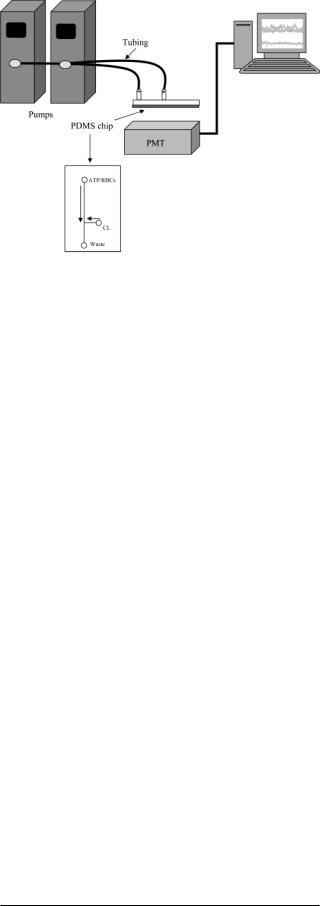
Figure 1. Setup for measuring ATP release from RBCs that are mechanically deformed in the microchip channels. The channels patterned in the microchip (derived from poly(dimethylsiloxane)) are shown below the schematic. Experimental details are described in the text.
RBCs were resuspended and washed three times in PSS. The RBCs were then diluted with the buffer to the appropriate hematocrit. For most studies reported here, a hematocrit of 7% was employed since the hematocrit of RBCs in resistance vessels is generally less than 20%.
PDMS Fabrication. PDMS channel structures were produced based on previously published methods.23,36 Briefly, masters for the production of PDMS microchannels were made by coating a 4-in. silicon wafer (Silicon, Inc., Boise, ID) with SU-8 10 negative photoresist (MicroChem Corp., Newton, MA) using a spin coater (Brewer Science, Rolla, MO) operating with a spin program of 2000 rpm for 20 s. The photoresist was prebaked at 95 °C for 5 min prior to UV exposure with a near-UV flood source (Autoflood 1000, Optical Associates, Milpitas, CA) through a negative film (2400 dpi, Jostens, Topeka, KS), which contained the desired channel structures. All channel structures were drawn in Freehand (PC version 10.0, Macromedia, Inc. San Francisco, CA). Following this exposure, the wafer was postbaked at 95 °C for 5 min and developed in Nano SU-8 developer (Microchem). The thickness of the photoresist was measured with a profilometer (Alpha Step200, Tencor Instruments, Mountain View, CA), which corresponded to the channel depth of the PDMS structures.
A 20:1 mixture of Sylgard 184 elastomer and curing agent (Ellsworth Adhesives, Germantown, WI) was used (in comparison to the normally used 10:1 mixture23,36) to increase the “stickiness” of the PDMS to aid in the reversible bonding procedure. This mixture was poured onto the silicon wafer and cured at 70 °C for2 h. After this time the PDMS layer was then pealed off the master. The general chip design depicted in Figure 1 was used for all studies reported here. The distance from the sample reservoir to the T intersection was 4.5 cm, and the distance from the T to the waste reservoir is 1.9 cm. For studies where ATP release from RBCs was measured, the channels were made to be 60 ím wide and 38 ím deep. These channel dimensions were
(36)Martin, R. S.; Gawron, A. J.; Lunte, S. M.; Henry, C. S. Anal. Chem. 2000, 72, 3196-3202.
also used to compare the ATP release from RBCs in channels to the ATP release from RBCs flowing through microbore tubing having an inside diameter of 50 ím. These widths were measured via an Olympus BX60M microscope (Olympus America, Melville, NY) at 200 with a Sony CCD camera (SSC-DC5OA) and SPOT software (Diagnostics Instruments, Sterling Heights, MI). The channel depth corresponds to the height of the master, which was measured with a profilometer.
A glass plate that had microbore tubing connectors attached was made in-house. Soda lime glass plates (7.0 cm wide, 10.25 cm long, 2 mm thick) were purchased from a local glass shop. Fluid access holes were made in the glass plate by a 1.5-mm diamond drill bit and a Dremel rotary tool (Dremel, Racine, WI). The syringe connector portion of a Luer adapter was removed with the Dremel rotary tool and accompanying cutting disk and epoxied to the opposite side of the glass with J. B. Weld (Sulfur Springs, TX). The epoxy was cured in an oven (75 °C) for 2 h. Once attached, the glass plate with Luer fitting was reversibly sealed to the PDMS fluidic network, so that either the end of the flow channels or reservoirs overlapped with the fluid access holes. The glass plates could be reused many times, as the fittings were firmly affixed to the glass and the reversible bonding procedure allowed them to be cleaned and resealed as necessary.
Passage of RBCs through Fabricated PDMS Microchips and the Measurement of ATP. The system for measuring ATP consists of five major components, namely, two syringe pumps (one for the luciferin/luciferase mixture and one for the RBC sample), the PDMS chip, a glass substrate with the appropriate fluid fittings, and a photomultiplier tube (PMT) housed in a lightexcluding box (Figure 1). One syringe pump (Eldex Laboratories, Oakland, CA) is programmable and is equipped with a 2-mL syringe. One of the syringe barrels was filled with luciferin/ luciferase and pumped to the chip. An ATP standard or an aliquot of RBCs was pumped by the second syringe pump using the same type of connections as described for the luciferin/luciferase mixture. To have easy access to the RBCs during the studies, a conventional syringe pump is used (Harvard Apparatus) employing a glass 500-íL gastight syringe. Previous experience with this type of syringe has proven that RBC sedimentation during the measurement portion of the analysis is not problematic. However, we have also found that insertion of a small magnetic stir bar into the syringe, and then agitation with a magnet once the RBCs are in the syringe, helps to minimize any cell sedimentation that does occur during the measurement portion of the analysis. The RBCs and luciferin/luciferase solution, pumped at a flow rate of 1.0 íL min-1 for the 60 38 ím channel, mix at an intersection of the two channels etched on the fabricated chip (Figure 1). The combined flow rate of the two solutions then propels the RBCs and the chemiluminescent product of the reaction of ATP with the luciferin/luciferase mixture past the PMT within seconds. For those studies comparing various channel dimensions, the linear rates were held constant such that the determining factor in the shear stress placed upon the RBCs was indeed due to the channel and not the linear rate of the sample through the channel. The detection limits for ATP in this flow-based assay are well below 1 íM, and there are no measurable interferences from the RBC matrix. In addition, microbore tubing having an inside diameter of 250 ím was used to deliver all reagents from the syringe barrels
Analytical Chemistry, Vol. 76, No. 16, August 15, 2004 4851

to the microchip channels. Previous studies in our laboratory have shown that there is no ATP release from RBCs flowing through such large-bore tubing. In addition, measurements of RBC-derived ATP in the absence of flow-induced mechanical deformation11 were performed to determine any basal levels of ATP. The resultant chemiluminescent signal was measured by placing the microchip assembly directly over the PMT housing. The intersection of the two channels was placed over a window in the housing such that detection of any chemiluminescence was measured immediately after the luciferin/luciferase mixture reacted with ATP. The opening to the PMT is large enough to measure the entire channel length after the mixing T (1.9 cm). The chemiluminescent signal was recorded using a data acquisition program written in-house (LabWindows/CVI, National Instruments, Austin, TX). Since the reagents are continuously pumped through the system, the resultant signal is a steady-state signal whose amplitude can be measured and averaged over a period of 60 s. Amounts of ATP released from the RBC samples were determined by comparison to values for standards prepared in the RBC suspension buffer on the day of study. Measurements of the standards were performed in triplicate, and the results from these standards were used to generate a working curve.
RESULTS AND DISCUSSION
On-Chip Chemiluminescent Determination of ATP. The microchips employed in this study were derived from PDMS and prepared as described above. The instrumental setup, including a magnified version of the general microchip design, for all ATP determinations is shown in Figure 1. It should be noted that numerous methods of sealing the PDMS-derived microchip to the glass substrate were attempted leading up to the final version discussed here. That is, it was initially thought that flow rates in the 1-10 íL min-1 range would not be possible with simple reversible sealing of the PDMS-derived chip to the glass substrate. Therefore, initial attempts employed a plasma cleaner to create an irreversible seal.23,24 This method has proven to be an affective technique for irreversibly sealing PDMS to either glass or another section of PDMS, especially for those applications where electrogenerated flow is employed. That is, in electrogenerated flow on microchips, the reservoir for reagents and samples consists of holes punched out of the PDMS-derived chip. Thus, upon removal of the chip and glass substrate from the plasma cleaner, there is no alignment to be performed. This allows the user to simply place the PDMS-derived chip immediately on the glass substrate.
Conversely, when employing hydrodynamic flow, where the chip channel has to be connected to the fittings delivering reagents and sample from the pump (typically a syringe pump), proper alignment is important. This proper alignment requires 8-10 s to align the channels with the fittings and seal the plasma-treated PDMS-derived microchip to the glass substrate. An incomplete seal will result if the alignment procedure requires more than 10 s.37 In an attempt to circumvent alignment problems, 2 mm 2 mm boxes were initially part of the chip design. The idea of boxes as part of the chip design is that it would allow for some error during the alignment procedure of the channel over the fluid
(37)Duffy, D. C.; McDonald, J. C.; Schueller, O. J. A.; Whitesides, G. M. Anal. Chem. 1998, 70, 4974-4984.
Figure 2. Chemiluminescent profiles resulting from the continuous flow of ATP standards and a 7% hematocrit of rabbit RBCs (gray scale trace) through a microchip having channel dimensions of 60 ím in width and 38 ím deep. The trace labeled as buffer is the intensity resulting from the analysis of the buffer in which the RBCs and standards were prepared. Based on the working curve generated from the standards shown, the ATP release from the RBCs was 2.22 ( 0.50 íM.
fittings. In other words, the boxes would allow for a faster alignment and, hopefully, a more complete seal of the microchip to the glass substrate. While this method did result in a better seal, the reproducibility of flow was reduced, and in fact, quite often some leaking around the boxes was witnessed.
Surprisingly, the best results were obtained by using a reversible seal technique. Here, the channels in the PDMS-derived microchip, which did not contain any reservoirs at the channel starting point, were simply aligned over the fluid connectors. Since a plasma treatment was not employed during the sealing process, speed was not an issue during the alignment process and boxes were not employed as part of the chip design. The use of a 20:1 PDMS/curing agent ratio may have aided in the strength of the reversible seal. The ability to generate flow through the microchip with a reversible seal is very advantageous for the types of studies reported here. For example, in addition to pushing RBCs through the microchip channels, the PSS used as the RBC diluent and carrier stream contains bovine serum albumin that can clog the microchip channels. Thus, when a clog does occur, reversible sealing of the PDMS microchip to the glass substrate enables the microchip channels and glass to be cleaned and reused for measurements. An irreversible seal would damage the PDMS microchip and require a completely new chip before further analysis could take place. Typically, an entire analysis, including calibration with standards, could be performed without any clogging problems.
Initial experiments using the PDMS microchip as part of the instrumental setup shown in Figure 1 indicated that ATP standards can be measured on-chip with chemiluminsescence detection. To obtain data using the chip design shown in Figure 1, ATP and a luciferin/luciferase mixture are delivered to the channels of the microchip at flow rates of 1.0 íL min-1 and the resultant chemilumescence signal is recorded by a PMT placed directly below the microchip assembly. Standards prepared in a buffered PSS having ATP concentrations of 0, 2, and 5 íM resulted in a calibra-
4852 Analytical Chemistry, Vol. 76, No. 16, August 15, 2004
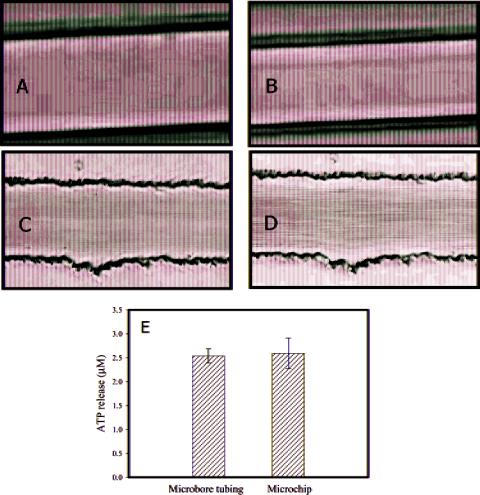
Figure 3. Comparing RBC flow through microbore tubing (A, B) and microchip channels (C, D). The amounts of ATP released from RBCs flowing through the microchip channels (2.59 ( 0.32 íM) and microbore tubing (2.54 ( 0.15 íM) are shown in (E). Details of the chip and tubing dimensions are described in the text. The error bars represent standard deviations of the set (n ) 3).
tion curve with a slope of 0.19 and an y-intercept of 0.47 (r2 ) 0.9993).
In vivo, ATP release from RBCs can result from multiple stimuli including hypoxia, acidosis (an environment with a low pH), and physical deformation. The physical stress arising from RBC flow through the channels can be changed by alterations in such flow parameters as channel diameter, channel length, and flow rate of the RBCs through the channels. Figure 2 shows the chemiluminescent signals from both ATP standards and ATP released from RBCs flowing through the channels. The 60-ím width is important since this type of width approximates the diameters of resistance vessels in vivo. Based on the calibration curve, the ATP release from this particular RBC sample was 2.22 ( 0.50 íM. A decrease in RBC-derived ATP release was measured (0.60 ( 0.07 íM) when an aliquot from the same RBC sample was pumped through the microchip having channel dimensions of 100 ím wide and 54 ím deep. These results are consistent with our previous findings that significant increasing amounts of ATP are released from RBCs as a function of decreasing tubing diameters.10,11 New working curves were constructed whenever the microchip channel dimensions were changed. Of course, the channel dimensions (60 38 ím and 100 54 ím) used to deform the RBCs may be governed by the narrowest dimension of the channel.
Unlike fused-silica microbore tubing, the channels in the PDMS chips used in these studies are not cylindrical. Rather, the channels are rectangular37 and therefore do not truly mimic the shape of a circulatory vessel in vivo. However, if the channels can still mimic the forces that the RBCs would be subjected to in vivo, then fabricated microchips would still be a valuable tool for investigating this particular physiological function of RBCs. To gain a better understanding of the RBC flow through the channels on a PDMS chip, micrographs were obtained at various channel dimensions and the RBC flow profiles were compared to those profiles obtained by employing fused-silica microbore tubing as the vessel mimic. The micrographs in Figure 3 show a 7% hematocrit of RBCs flowing through microchip channels and microbore tubing. In each case, the flow rates were adjusted in order to see the effect of flow rate and channel dimensions on the RBC flow profile. Figure 3A shows a 7% hematocrit of RBCs flowing through microbore tubing (75-ím i.d.) at a flow rate of 5 íL min-1 while Figure 3B shows the RBCs flowing through the same tubing at 15 íL min-1. In each case, there is a cell free layer, often called a “skimming layer”, along the walls of the tubing. This cell-free layer arises due to the non-Newtonian properties of the RBCs. That is, the RBCs undergo an axial drift toward the center of the tubing (known as the magnus effect) where the
Analytical Chemistry, Vol. 76, No. 16, August 15, 2004 4853