Материал: 9332
DISCRETE SEMICONDUCTORS
BGY114D; BGY114E
UHF amplifier modules
Product specification |
1996 Jun 04 |
Supersedes data of April 1994
File under Discrete Semiconductors, SC09
Philips Semiconductors |
Product specification |
|
|
|
|
UHF amplifier modules |
BGY114D; BGY114E |
|
|
|
|
FEATURES
·12.5 V nominal supply voltage
·6 W output power
·Easy control of output power by DC voltage.
APPLICATIONS
·Personal Mobile Radio (PMR) equipment operating in the 800 to 870 MHz and 890 to 950 MHz frequency ranges.
DESCRIPTION
The BGY114D and BGY114E are five-stage UHF amplifier modules in a SOT278A package. Each module consists of 5 NPN silicon planar transistor dies mounted together with matching and bias circuit components on a metallized ceramic substrate.
QUICK REFERENCE DATA
RF performance at Tmb = 25 °C.
PINNING - SOT278A
PIN |
DESCRIPTION |
|
|
1 |
RF input |
2 |
VS1 |
3 |
VC |
4 |
VS2 |
5 |
RF output |
Flange |
ground |
|
|
|
1 |
2 |
3 |
4 |
5 |
Top view |
|
|
|
MSA488 |
|
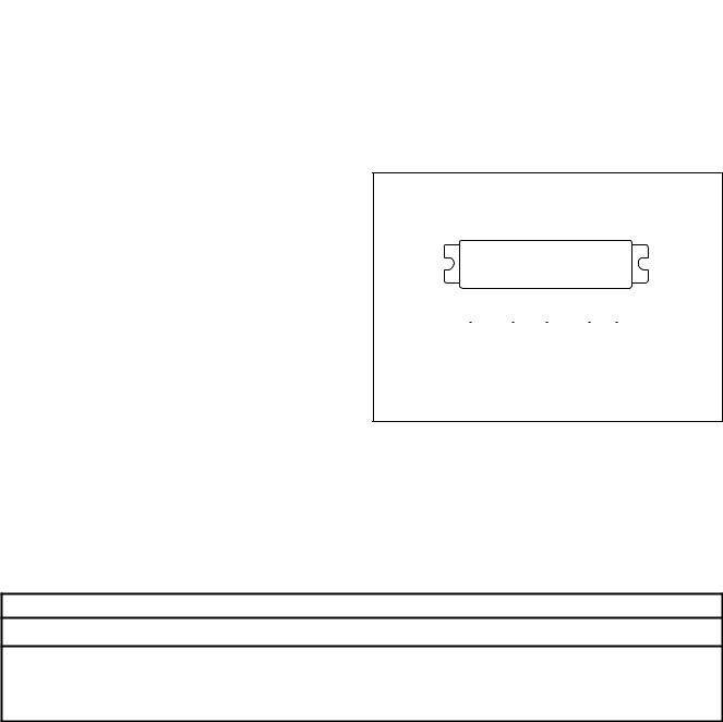
Fig.1 Simplified outline.
TYPE |
MODE OF |
f |
VS1 |
VS2 |
PL |
Gp |
h |
ZS; ZL |
NUMBER |
OPERATION |
(MHz) |
(V) |
(V) |
(W) |
(dB) |
(%) |
(W) |
|
|
|
|
|
|
|
|
|
BGY114D |
CW |
800 to 870 |
8 |
12.5 |
6 |
³37.8 |
typ. 40 |
50 |
|
|
|
|
|
|
|
|
|
BGY114E |
CW |
890 to 950 |
8 |
12.5 |
6 |
³37.8 |
typ. 40 |
50 |
WARNING
Product and environmental safety - toxic materials
This product contains beryllium oxide. The product is entirely safe provided that the BeO disc is not damaged. All persons who handle, use or dispose of this product should be aware of its nature and of the necessary safety
precautions. After use, dispose of as chemical or special waste according to the regulations applying at the location of the user. It must never be thrown out with the general or domestic waste.
1996 Jun 04 |
2 |
Philips Semiconductors |
|
Product specification |
||
|
|
|
|
|
UHF amplifier modules |
BGY114D; BGY114E |
|||
|
|
|
|
|
LIMITING VALUES |
|
|
|
|
In accordance with the Absolute Maximum Rating System (IEC 134). |
|
|
|
|
|
|
|
|
|
SYMBOL |
PARAMETER |
MIN. |
MAX. |
UNIT |
|
|
|
|
|
VS1 |
DC supply voltage |
− |
9 |
V |
VS2 |
DC supply voltage |
− |
16 |
V |
VC |
DC control voltage |
− |
9 |
V |
PD |
input drive power |
− |
3 |
mW |
PL |
load power |
− |
10 |
W |
Tstg |
storage temperature |
−40 |
+100 |
°C |
Tmb |
operating mounting base temperature |
−30 |
+100 |
°C |
12 |
|
|
MBD360 |
|
|
|
|
PL |
|
|
|
(W) |
|
|
VSWR = 1:1 |
10 |
|
|
|
8 |
|
|
|
|
|
VSWR = 3:1 |
|
6 |
|
|
|
4 |
|
|
|
2 |
|
|
|
0 |
|
|
|
0 |
40 |
80 |
120 |
|
|
|
Tmb (oC) |
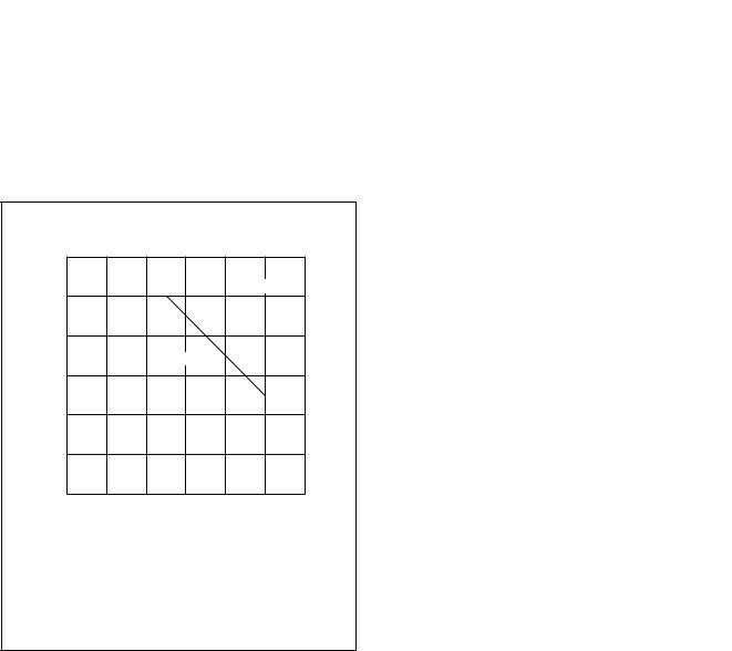
Fig.2 Power derating curve.
1996 Jun 04 |
3 |

Philips Semiconductors |
Product specification |
|
|
UHF amplifier modules |
BGY114D; BGY114E |
|
|
CHARACTERISTICS
ZS = ZL = 50 W; PD = 1 mW; VS1 = 8 V; VS2 = 12.5 V; VC £ 8 V; Tmb = 25 °C; unless otherwise specified.
SYMBOL |
PARAMETER |
CONDITIONS |
MIN. |
|
TYP. |
MAX. |
UNIT |
|
|
|
|
|
|
|
|
f |
frequency |
|
|
|
|
|
|
|
BGY114D |
|
800 |
|
- |
870 |
MHz |
|
BGY114E |
|
890 |
|
- |
950 |
MHz |
IQ3 |
leakage current |
VS1 = VC = 0; PD = 0 |
- |
|
- |
1 |
mA |
PL |
load power |
|
6 |
|
- |
- |
W |
Gp |
power gain |
adjust VC for PL = 6 W |
37.8 |
|
- |
- |
dB |
h |
efficiency |
adjust VC for PL = 6 W |
30 |
|
40 |
- |
% |
H2 |
second harmonic |
adjust VC for PL = 6 W |
- |
|
- |
-35 |
dBc |
H3 |
third harmonic |
adjust VC for PL = 6 W |
- |
|
- |
-35 |
dBc |
VSWRin |
input VSWR |
adjust VC for PL = 6 W |
- |
|
- |
3 : 1 |
|
DG |
gain control |
VC = 0 to 8 V |
30 |
|
- |
- |
dB |
|
stability |
PD = -3 to +3 dBm; VS2 = 10 to 16 V; |
- |
|
- |
-60 |
dBc |
|
|
VC = 0 to 8 V; PL £ 7 W; VSWR £ 3 : 1 |
|
|
|
|
|
|
ruggedness |
VS2 = 16 V; PL £ 7 W, duration |
|
no degradation |
|
||
|
|
1 minute; VSWR £ 20 : 1 |
|
|
|
|
|
|
|
|
|
|
|
|
|
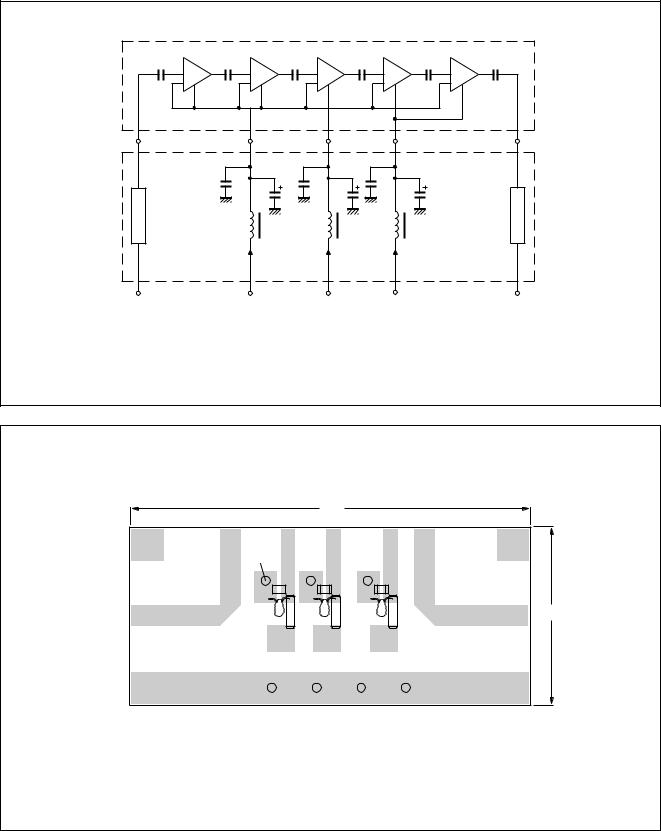
List of components (see Fig.3)
COMPONENT |
DESCRIPTION |
VALUE |
DIMENSION |
CATALOGUE NO. |
|
|
|
|
|
C1, C3, C5 |
multilayer ceramic chip capacitor; note 1 |
1 nF |
- |
- |
|
|
|
|
|
C2, C4, C6 |
tantalum capacitor |
1 mF; 35 V |
- |
- |
L1, L2, L3 |
Ferroxcube chip bead; grade 4S2 |
- |
- |
4330 030 36300 |
|
|
|
|
|
Z1, Z2 |
stripline; note 2 |
50 W |
width 4.7 mm |
- |
Notes
1.ATC capacitor type 100B or capacitor of same quality.
2.The striplines are on a double copper-clad printed-circuit board with PTFE fibre-glass dielectric (er = 2.2); thickness 1¤16 inch.
1996 Jun 04 |
4 |
Philips Semiconductors |
Product specification |
|
|
UHF amplifier modules |
BGY114D; BGY114E |
|
|
handbook, full pagewidth
1 |
2 |
|
3 |
4 |
|
5 |
|
C2 |
C3 |
C4 |
C6 |
|
|
|
C1 |
C5 |
|
|
||
Z1 |
L1 |
|
L2 |
L3 |
|
Z2 |
|
|
|
|
|||
|
I = 110 mA |
|
I = 65 mA |
I = 1.15 mA |
|
|
|
typical |
|
typical |
typical |
|
|
RF input |
VS1 |
|
VC |
VS2 |
MBD373 |
RF output |
Fig.3 Test circuit.
90
handbook, full pagewidth
rivet |
|
|
|
|
C1 |
|
C3 |
|
C5 |
Z1 |
|
|
|
Z2 |
C2 |
C4 |
|
C6 |
40 |
|
L1 |
L2 |
|
|
|
|
L3 |
||
VS1 |
|
VC |
|
VS2 |
|
|
|
|
MBD357 |
Dimensions in mm.
Fig.4 Printed-circuit board component layout.
1996 Jun 04 |
5 |