Материал: Russian Journal of Building Construction and Architecture

BUILDING STRUCTURES,BUILDINGS AND CONSTRUCTIONS
UDC 624.04
S. B. Kositsyn1, V. S. Fedorov2, Tran Xuan Linh3
ANALYSIS OF VARIOUS MODELS OF FOUNDATION, AMBIENT CYLINDRICAL
SHELL WITH A VIEW OFTHE POSSIBILITY
OF DETACHMENT FROM A SHELL
Moscow State University of Railway Engineering Nicolay II(MIIT) Russia, Moscow, tel.: (499) 978-16-73, e-mail: kositsyn-s@yandex.ru 1D. Sc. in Engineering, Prof., Head of the Dept. of Theoretical mechanics
2D. Sc. in Engineering, Prof., Head of the Dept. of building design, buildings and buildings Institute of Research and Development, Duy Tan University, Vietnam, Danang
3Tran Xuan Linh, PhD
Statement of the problem. The work is aimed at solving problems of contact interaction of cylindrical shells with surrounding arrays of soils in underground structures.
Results. Based on our previous study the authors developed methods that takes into account the unilateral contact interaction of shell and soil foundation, allowing to compare three models of the ground surrounding the shell: the foundation Fuss – Winkler, model of elastic layer and a volumetric array. An accurate formula for the elastic modulus of the elastic layer three-dementional array is provided.
Conclusions. The results of the shell in the system "shell – surrounding ground", obtained by the three considered models of soil are in good agreement with each other both qualitatively and quantitatively, which indicates the reliability of the constructed models and calculation. Displacements, stresses and strains of the shell, and areas of detachment of soil in all the calculated cases are almost identical. The model of the elastic layer should be applied in the absence of finite elements for modeling the elastic foundation, or by the irregularity of the shape of finite elements of the shell. When choosing a thickness of the elastic layer should not make it too thick. In practice one should primarily use three-dimensional models of the soil with a rigid unilateral contact elements to account for the detachment from the shell.
Keywords: cylindrical shell, soil array, elastic foundation, elastic layer, flat, three-dimensional and contact finite elements.
Introduction
One of the pressing issues of the development of technology is a wide application of easy and cost-effective wall-thinned structures. These systems are commonly used in construction of
© Kositsyn S. B., Fedorov V. S., Tran Xuan Linh, 2017
6
Issue № 2(34), 2017 |
ISSN 2542-0526 |
buildings and underground structures, pipelines, railway and highway tanks as well as ship and aircraft building, chemical and energy machine building, gas, oil and other industries. The major elements of these structures are cylindrical shells. For different types of laoding particularly in the intersection of shells there are significantly heterogeneous stress strains that typically have high levels of concentration of strains and thus there must be a special focus on accurate calculation methods that allow the resources of strength to be evaluated and a construction material to be highly reliable. Therefore this kind of research is essential these days.
Problems of contact of cylindrical shells and their intersections with surrounding soils in underground structures has not been sufficiently studied. Soils are not just a load but an environment where deformations occur. Therefore a lot of attention is given to contact of shells with soil. Presently in order to address this issue, flat calculation models are commonly used that are designed by cutting out of an actual spatial system by two longitudinal sections that are a length unit away from each other. In a flat model a shell is regarded as a rod system of a thickness unit and soil as a flat system or the Winkler-Fuss base. However, for underground objects with a complex geometry this problem cannot be formulated in such a way [1]. Note some studies dedicated to interactions of a cylindrical shell with soil (it is regarded as an elastic Winkler-Fuss base) [2, 3, 4, 5].
Analytical methods only use a non-complex geometry with simple boundary conditions and simplest behavior of materials. In [6] based on the use of operational calculation associated with the Laplace transform, analytical solutions for an isolated cylindrical shell with an elastic filler modelled using the Winkler-Fuss model with different boundary conditions for an axial symmetrical load are presented.
In [7] a method of calculating stress-strains of underground thin-walled melioration pipelines that considers a spatial nature of their operation and features of interactions of a pipeline and elastic soil under the impact of external loads.
One of the most effective and common numerical methods is the finite element method. Recently in order to analyze the stress-strain of the “shell-soil” system, latest finite element sets have been used to allow to consider a spatial nature of interactions of shells with surrounding soils. The results of calculating underground main pipelines using the finite element method are reported in publications in this country and abroad [8––16]. In these studies calculation schemes are complex, i.e. they include models of a pipe wall and in some cases contact layers between the pipe wall and soil as well.
7
Russian journal of building construction and architecture
However, it is still unclear how to connect the characteristics of different models of soil foundations considering the soil possibly sticking off the shell in order to get the results that could be compared while using the models.
The aim of this paper is to develop and improve calculation models of cylindrical shells interacting with the surrounding soil given it possibly sticking off and the methods that allow the characteristics of the resulting models to be connected.
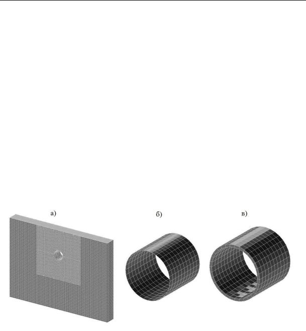
The study is performed using the example of a circle cylindrical shell with the radius of thickness of 0.02 m made of steel with the elasticity modulus Eоб = 2 · 1011 n/m2, the Poisson coefficient об = 0.3 and the density об = 7800 kg/m3. The shell is placed into the soil at the depth of 5 m (Fig. 1а). In order to approximate the soil considering that it might stick off the shell, let us design three spatial models of varying complexity, study its features and find a connection between the parameters of the models in order to obtain valid and consistent calculation results.
Fig. 1. Finite element model of the “shell-soil” system: а) a shell with a volumetric massive modelling soil;
b)a shell with GAP elements that replace an elastic foundation;
c)a shell with the approximated elastic layer
1.Cylindrical shell interacting with the surrounding volumetric soil massive
Soil is modelled using a homogeneous three-dimensional massive with the following characteristics: the deformation modulus Eгр = 1.634 · 109 n/m2, coefficient of longitudinal deformations гр = 0.3. The shell and soil materials were considered infinitely linearly elastic.
8
Issue № 2(34), 2017 |
ISSN 2542-0526 |
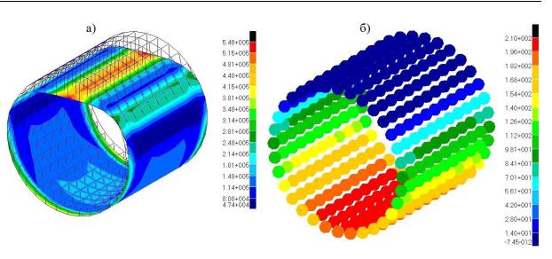
The sizes of the calculation region of the massive were accepted considering attenuation of the stress-strain of soil with 5 diameters of the shell to each side and down [17, 18]. A finite element complex MSC PATRAN –– NASTRAN was sued for the calculation. The shell is approximated with two-dimensional flat four-node elements based on the hypothesis of straight normal with six degress of freedom in each node. The sizes of the elements are 0.2 0.2 m. A volumetric massive modelling the soil is presented with three-dimensional finite elements in the shape of four-node tetrahedrons (a thick net next to the shell) and eight-node parallelepipeds (a rarer net next in the remaining parts of the massive) with three degrees of freedom in each node. The use of tetrahedrons is due to the fact that the geometry of the massive is rather complex at the place of a hole supported by the shell. The calculation region is supported from displacements normal to the surfaces of the massive, along the face, sides and down. The shell along its faces has identical supports to keep the calculation model geometrically stable. In order to be able to consider that the soil might stick off the soil, between the shell and massive there are special cotnanct elements [19] with the different tension and compression and tension stiffness (in the NASTRAN software they are called GAP elements). They have zero lengths and go to infinity and equalled (Sр = 10-7 n/m). Their compression stiffness went to infinity and were accepted to be Sсж = 107 n/m. The calculation was performed in a constructionally non-linear setting (using the method of sequential approximations these areas were investigated) to establish the impact of the shell’s own weight. The eigen weight of soil is not taken into account. The results of the calculations led to a model of the stress-strain. The maximum complete transformations wmax and maximum equivalent von Mises strain [20] in the internal вequiv and outside нequiv fibres of the shell are identified in Table (column “Variant 1”. Fig. 2a depicts a deformed shell and a field of equivalent strains in its external rings. Fig. 2b shows a field of effort in contact elements.
|
|
|
|
|
|
|
Table |
|
Maximum displacements and equivalent strains in the shell |
|
|
||||
|
|
|
|
|
|
|
|
Stress-strain parameter |
Variant 1 |
Variant 2 |
Variant 3 |
Variant 3 |
Variant 3 |
Variant 3 |
Variant 3 |
(tпр = 0.08 m) |
(tпр = 0.1 m) |
(tпр = 0.2 m) |
(tпр = 0.3 m) |
(tпр = 0.4 m) |
|||
|
|
|
|
|
|
|
|
wmax, 10-5m |
7.8164 |
7.6874 |
8.0483 |
8.0454 |
8.0316 |
8.0176 |
8.0628 |
|
|
|
|
|
|
|
|
вэкв, 105 n/m2 |
5.1381 |
5.0986 |
5.1358 |
5.1376 |
5.1366 |
5.1282 |
5.1389 |
|
|
|
|
|
|
|
|
нэкв, 105 n/m2 |
5.4799 |
5.5400 |
5.6483 |
5.6484 |
5.6440 |
5.6338 |
5.6443 |
|
|
|
|
|
|
|
|
9
Russian journal of building construction and architecture
Fig. 2. Stress-strain for the shell connecting the following with the volumetic massive: а) deformed type and intensity fields of von Mises in external Variant;
b)efforts and contanct elements
2.Cylindrical shell contacting an elastic foundation
The second calculation scheme is the following. The soil surrounding the shell is modelled using the elastic Winkler-Fuss base hat might stick off it (Fig. 1b). Since as well as in NASTRAN there is no model of such an elastic base, it is replaced with special contact elements (GAP elements) operating only during compression. The length of the GAP elements are accepted to be zero. The number of the GAP elements is determined with that of the nodes in the grid of the shell elements. The stiffness of the GAP elements during tension was accepted to strive for zero (Sр = 10-7 n/m) as well as in the previous model and the stiffness of the GAP elements during compression was calculated using the formula [19]:
Sсж Kab .
Here K is the coefficient of the subbase of the elastic base; a and b are linear sizes of the finite elements of the shell (in this case a b 0.2 m).
The stiffness of the GAP elements placed near the face of the shell is accepted to be twice as small as that of the remaining GAP elements as the face finite elements of the shell adjoin the corresponding GAP elements from two but not four sides.
In order to determine the coefficient of the subbase of the elastic base corresponding with the volumetric massive discussed above, the following extra calculation was performed. A threedimensional massive modelling the rod of the base (Eгр = 1.634·109 n/м2, гр = 0.3) in the plan
10