Материал: Russian Journal of Building Construction and Architecture

Russian journal of building construction and architecture
8.Aynbinder A. B. Raschet magistral'nykh i promyslovykh truboprovodov na prochnost' i ustoychivost' [Calculation of main and field pipelines on the strength and stability]. Moscow, Nedra Publ., 1991. 288 p.
9.Aleshin V. V., Seleznev V. E., Klishin G. S., etc, Aleshin V. V., Seleznev V. E., eds. Chislennyy analiz prochnosti podzemnykh truboprovodov [Numerical analysis of strength of underground pipelines]. Moscow, Editorial URSS Publ., 2003, 320 p.
10.Lalin V. V., Yavarov A. B. Sovremennye tekhnologii rascheta magistral'nykh truboprovodov [Modern technology of calculation of the main pipelines]. Inzhenerno-stroitel'nyy zhurnal, 2010, no. 3, pp. 43––47.
11.Seleznev V. E., Aleshin V. V., Pryalov S. N. Osnovy chislennogo modelirovaniya magistral'nykh truboprovodov [Basics of numerical modeling of pipelines]. Moscow, KomKniga Publ., 2005. 496 p.
12.Zienkiewicz O. C., Taylor R. L. The finite element method. 5-th edition. Butterworth-Heinemann, 2000, vol. 2: Solid mechanics. 479 p.
13.Altaee A., Fellenius B. H. Finite element modeling of lateral pipeline-soil interaction. 14th International Conference on Offshore Mechanics and Arctic Engineering. OMAE 96. Florence, 1996.
14.Nobahar A. Effect of soil spatial variability on soil-structure interaction: thesis Doctor of Philosophy. St. John. Canada, 2003. 305 p.
15.Phillips R., Barrette J., Jafari A., Park T., Piercey G. Pipeline integrity for ground movement hazards. Canada, 2008. 154 p.
16.Popescu R., Nobahar A. 3D Finite element analysis of pipe-soil interaction effects of groundwater. St. John, Canada, C-CORE, 2003. 34 p.
17.Savin G. N. Raspredelenie napryazheniy okolo otverstiy [The distribution of stresses around holes]. Kiev, Naukova Dumka Publ., 1968. 891 p.
18.Chan Suan Lin'. Otsenka razmerov massiva grunta, zadavaemogo pri prostranstvennykh raschetakh podzemnykh sooruzheniy, iskhodya iz usloviy zatukhaniya ego napryazhenno-deformirovannogo sostoyaniya [The assessment of the magnitude of the soil specified for the spatial calculations of underground structures, based on the conditions of damping of its stress-strain state]. Stroitel'naya mekhanika inzhenernykh konstruktsiy i sooruzheniy, 2013, no. 4, pp. 41––43.
19.Kositsyn S. B., Dolotkazin D. B. Raschet sterzhnevykh sistem, vzaimodeystvuyushchikh s uprugim osnovaniem, metodom konechnykh elementov s ispol'zovaniem programmnogo kompleksa MSC/NASTRAN FOR WINDOWS [Calculation of rod systems interacting with an elastic Foundation, finite element method using the software complex MSC/NASTRAN FOR WINDOWS]. Moscow, MIIT, 2004. 116 p.
20.Aleksandrov A. V., Potapov V. D. Osnovy teorii uprugosti i plastichnosti [Fundamentals of the theory of elasticity and plasticity]. Moscow, Vysshaya shkola Publ., 1990. 400 p.
21.Kositsyn S. B. Neklassicheskie krivolineynye konechnoelementnye modeli v lineynykh i ne-lineynykh zadachakh stroitel'noy mekhaniki. Diss. dokt. tekhn. nauk [Non-classical curvilinear finite element models in linear and nonlinear structural mechanics problems. Dr. eng. sci. diss.]. Moscow, MIIT,1993. 424 p.
22.Seredin P. V., Glotov A. V., Domashevskaya E. P. e. a. Structural and spectral features of MOCVD AlxGayIn1-x-yAszP1-z/GaAs (100) alloys. Semiconductors, 2012, vol. 46, iss. 6, pp. 719––729.
16

Issue № 2(34), 2017 |
ISSN 2542-0526 |
HEAT AND GAS SUPPLY,VENTILATION,AIR CONDITIONING,
GAS SUPPLY AND ILLUMINATION
UDC 621.039:697.34
V. N. Mel'kumov1, S. V. Chuikin2, A. I. Kolosov3
DISTRICT HEATING FROM NUCLEAR POWER STATIONS
Voronezh State University of Architecture and Civil Engineering Russia, Voronezh, tel.: (473)271-53-21, e-mail: teplosnab_kaf@vgasu.vrn.ru
1D. Sc. in Engineering, Prof., Head of the Dept. of Heat and Gas Supply and Oil and Gas Business Russia, Voronezh, tel.: (473)271-53-21, e-mail: ser.chu@mail.ru
2PhD in Engineering, Assoc. Prof. of the Dept. of Heat and Gas Supply and Oil and Gas Business Russia, Voronezh, tel.: (473)271-53-21, e-mail: teplosnab_kaf@vgasu.vrn.ru
3PhD in Engineering, Assoc. Prof. of the Dept. of Heat and Gas Supply and Oil and Gas Business
Statement of the problem. The limited proven reserves of energy resources lead to the need for a wider use of nuclear energy for heat supply of cities. Therefore studying the possible schemes of district heating from nuclear sources is becoming increasingly important and most promising as it is capable of making up for a growing shortage of generating capacity.
Results and conclusions. The article considers thermal schemes of nuclear power plants heat and atomic power plants, as well as lists the parameters of their main units. This data can be used as an input when searching for the most optimal modes of work stations so that through more profound analysis ways to improve the basic circuits of nuclear power stations could be identified. The method of increasing the economic efficiency of nuclear stations of a heat supply based on a joint work with peak boiler-houses lo-cated in the center of heat loads is set forth.
Keywords:heatpowerengineering,heatsupply,nuclearenergy,nuclearstationsof heatsupply, atomic powerplant.
Introduction
Currently fuel has become one of the defining factors of production. A good illustration of the key role of fuel and energy base of the global economy is a so-called energy crises that has made this issue one pressing and global. The emerging energy situation is associated with a rapid decrease in the body of non-renewable reserves of oil, and later on gas, which causes
© Mel'kumov V. N., Chuikin S. V., Kolosov A. I., 2017
17
Russian journal of building construction and architecture
increasing costs as they are being sought after. The response to the energy crises was the development of a strategy for the utilization of fuel and energy based on energy saving and optimization of the structure of fuel and energy resources. It is obvious that in these conditions the share of nuclear energy in fuel-energy balance will steadily increase. The decline of the level of confidence in the nuclear energy after the accident at the Chernobyl nuclear power plant and an increasing reliability of modern designs of nuclear reactors contributed to the change in the tendency of the reduction in the share of nuclear energy in the global balance promote its growth.
The most common are power reactors to generate the electricity in nuclear power plants (NPPs). In the process of the development of atomic energy, a number of different thermal schemes of nuclear power plants (NPP) were suggested. However, the experience of the development of heat schemes of nuclear power plants was the foundation of a further improvement of nuclear installations and thermal equipment. At the same time, the thermal energy characteristic of the Northern territories is in growing demand. For example, in addition to the existing nuclear power plants (ATEC) located in the Chukotka Autonomous District (Bilibino NPP), the construction of a plant for the supply of Arkhangelsk and Severodvinsk is being planned. A floating plant for its Northern territories is being developed as well.
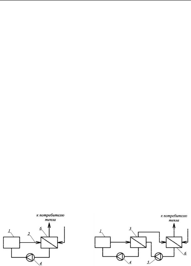
These nuclear facilities for the generation of heat associated with the end-point user via a heat exchanger. The principal scheme of such a setup is shown in Fig. 1. The setup includes a reactor, a piping system, relational pump. In a one-contour loop the heat exchanger flows the same coolant installed in the reactor. In this case, the coolant has a large induced radioactivity and in some cases may contain a radioactive fission product. During the decompression of the heat exchanger radioactive materials will penetrate the end-point contour.
To the |
|
To the |
end-point user |
|
end-point user |
Fig. 1. Single-loop (a) and bypass (b) nuclear power plant for heat supply: 1 — nuclear reactor; 2 — pipe; 3 — intermediate heat exchanger;
4, 5 –– circulation pumps of the first and second contours; 6 — end-point exchanger
18
Issue № 2(34), 2017 |
ISSN 2542-0526 |
One-contour setups cannot be used when contamination it is not permitted to pollute a coolant circuit of the consumer. Therefore, the practical use is made of a multi-circuit setup where transfer of heat to the external consumer makes use of two or more coolants not contacting with each other directly. In Fig. 1b the reactor with an intermediate heat exchanger forms the first closed loop and the intermediate heat exchanger, piping and terminal heat exchanger do the second circuit. Each circuit has its own circulating pump.
In multi-loop setups there is hardly any contact of the active coolant of the first circuit to the operating environment of the consumer. However, the implementation of a multicontour setup is more complicated, since additional hardware is required. In addition to the special stations for heat supply, some nuclear power plants might be utilized. E.g., in Leningrad and Beloyarsk NPP in addition to generating electrical energy there is also a low-grade heat and hot water for adjoining communities. However, the maximum performance of thermal energy is observed for ATEC and nuclear stations of heat supply (NSHS).
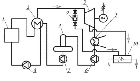
1. Schematic diagram of the nuclear steam plant. Nuclear thermal electric pipeline generates electricity and simultaneously through the network heaters releases heat to consumers. The steam for heating water in a network is directed from a heater that is controlled from the selection of the turbine (Fig. 2).
Into the heating network
Fig. 2. Scheme of ATEC:
1 is a reactor; 2 is a steam generator; 3 is a turbine; 4 is a deaerator; 5 is a condenser; 6 is a condensation pump; 7 is a feed pump; 8 is a circulating pump; 9 is a reduction-cooling setup; 10 is a heater of nuclear water
19

Russian journal of building construction and architecture
To satisfy the peak heat demand a reduction-cooling setup 9 is used. Steam and heat balances of the plant are determined by the following expressions
G = Gn + Gk , |
(1) |
Nэ = N n + Nk , |
(2) |
where G is the total steam flow to the turbine; Gn is the steam consumption selected to meet thermal demands; Gk is the consumption of steam sent to the condenser; Nn is the electrical power produced by the steam selection; Nk is the electrical power produced by the steam entering the condenser.
The most efficient ratio of the produced heat and electric energy is determined by calculating the thermal efficiency using the following expressions. The efficiency of an ATEC:
|
АТЭЦ |
|
QИСП |
|
Nэ QТ.П. |
, |
(3) |
|
|
|
Q |
|
Q |
р |
|
||
|
|
|
ЗАТР |
|
|
|
||
where QТ.C. is the amount of heat sent to the consumer; Qр is the amount of the thermal energy of the power of the reactor.
The efficiency of the production of thermal energy:
|
QТ.П. |
· |
пг |
· |
mp1 |
· |
mp2 |
· |
m.c. |
, |
(4) |
Т.П. |
p |
|
|
|
|
|
|
||||
|
QТ.Р. |
|
|
|
|
|
|
|
|
|
|
where QТ.R. is the amount of thermal energy for the production QТ.C.; ηт. с. is the amount of heat losses in heating networks;
The efficiency of the production of thermal energy at an ATEC:
ЭАТЭЦ |
NЭ |
. |
(5) |
|
Qp QТ.П. / Т.П. |
||||
|
|
|
In some cases the index of the specific production of thermal energy for meeting a demand for heating is used:
ЭТП |
NЭТП |
, |
(6) |
|
Q |
||||
|
|
|
||
|
Т.П. |
|
|
where NETC is the amount of thermal energy that is released by the steam by the selection for a heating demand as well as that for heating provisional water.
In the above scheme the plant thermal energy of nuclear fission is perceived by thermal carriers of the first circuit. Let us consider in more detail the composition of the coolant equipment, e.g. the installation of a reactor VVER-1000 has much in common with the first contours of ATEC for different purposes.
20