Материал: Russian Journal of Building Construction and Architecture

Russian journal of building construction and architecture
Some known dynamic models do not allow one to obtain a generalized model due to a complex assembly, mode of operation of compactors or complexity of the models considering the structure of a specific device. There might be or not be angular oscillations of the masses, some inertia loads, dynamic features of transmission, the number of compactors facing compactng materials, etc. But the major disadvantages of these models is not presented as an element with the physical and mechanical properties of a corresponding material being compacted. Even when it is not attempted [1, 21], the best-case scenario would be to have this material being presented with elastic, viscous and plastic elements whose parameters cannot actually be determined independently of one another.
Hence all the known dynamic models of the interaction of the machines with compacting materials do not allow one to evaluate actual dynamic characteristics of the “machineenvironment”, i.e. to perform a quantitative evaluation.
1. Generalized dynamic model of the interaction of road construction materials with compacting elements of road construction machinery. Based on the use of the methods of formalizing dynamic systems, a generalized dynamic model of the interaction of different compactors with road asphalt concrete mixes and soils and using it a few specific models were obtained by equaling to zero the corresponding coefficients of differential equations or excluding some parts of the system equations.
Any technology of compacting road construction materials involves choice and use of a corresponding compacting machinery. E.g., in order to achieve the required standards of the density of soils in the construction of a subbase, a type of a compaction machinery and functional parameters of its operating body (amplitude and frequency of oscillations, static or dynamic contact pressure) should comply with a type of a subbase, its condition and required standards of compaction [9]. The same requirements apply for compacting machinery designed for compacting asphalt concrete mixes as well.
However, the amplitude of oscillations of any compactor depends on the physical and mechanical properties of a material being compacted and changes in the process. Therefore the suggested amplitudes of oscillations in the technical characteristics of compacting machinery should be adjusted to match the rheological properties of a material.
Any technology is designed to suit corresponding operating conditions and a contact of machinery with the environment. Thus it is impossible to start designing a compaction technology without being informed on the parameters or physical and mechanical characteristics of a material being compacted itself. The latter should be tested on site.
36
Issue № 2(34), 2017 |
ISSN 2542-0526 |
The major physical and mechanical characteristics of a compacted road construction material can be linear, volumetric or shear deformation. In order to describe the characteristics of a deformed environment with noticeable elastic-viscous-plastic properties that are non-linear and independent on time and nature of the interaction of the engines with the foundation, the Boltzman hereditary integral should be employed.
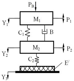
Fig. 1 shows a generalized dynamic model of different compaction machinery using rheological parameters of a compacted environment identified using the hereditary integral of elastic- viscous-plastic materials. This model allows the amplitude of oscillations and the capacities of compacting road asphalt concrete mixes and foundations for the tools selected to be used for compaction to be determined.
М1 and М2 are oscillating masses (the frame and carrier of the car);
С1 and С2 are the coefficients of elastic resistance; В is the coefficient of viscous friction;
РВ is the inertialess vertical load component from the operating bodies of the machinery; Рi are the external dynamic loads;
Е/ is the physical and mechanical parameter that characterizes the properties of a deformed base; Yi are vertical coordinates of the masses and surface of a compacted layer during the movement
of the compaction machinery
Fig. 1. Generalized dynamic model of compaction machinery for assessing the parameters of vertical oscillations
The model does not allow for the transmission that might come down to the schemes for calculating vertical oscillations of a full-track and wheeled tractors, heavy-duty vehicles, cars, etc. The results of the analysis of dynamic models of compacting machines are presented in Table where the plus sign indicates this element is present in the model and the minus sign shows there is not any.
The generalized two-mass dynamic model (Fig. 1) is described with a system of two linear differential second-order equations:
М1у1 В у1 у2 С1 у1 у2 РВ Р1, |
|
|
||||||
|
|
|
К |
К |
|
|
|
(1) |
|
|
В у1 у2 |
2 |
С1 у1 у2 Р2 |
, |
|||
М2 |
у2 |
1 |
|
|
||||
К1 К2 |
|
|||||||
|
|
|
|
|
|
|||
37

Russian journal of building construction and architecture
where
|
|
|
|
|
К1 С2 Y2 Y3 ; |
|
|
|
||
|
|
|
t |
|
|
|
t |
|
|
|
|
|
|
|
|
S t d |
|
|
|
|
|
К2 |
Е/ Y2 |
|
|
Y2 |
Y3 |
|
Y3 |
S t d |
; |
|
|
|
|
0 |
|
|
|
0 |
|
|
|
S(t – τ) is a relaxation nuclear characterizing hereditary properties of a material; t – τ is a period of time between the moment of observation of the deformation and moment of load application; Е/ is a physical and mechanical parameter of a compacted material that reflects the deformation modulus per unit of the thickness of a compacted layer, N m-1:
|
Е |
Е F |
|
|
|
|
|
|
|
|
|
|
|
||
|
|
к |
. |
|
|
|
|
|
|
|
|
|
(2) |
||
|
(t) h |
|
|
|
|
|
|
|
|
|
|||||
|
|
|
сл |
|
|
|
|
|
|
|
|
|
|
|
|
|
|
|
|
|
|
|
|
|
|
|
|
|
|
Table |
|
Results of analyzing dynamic models of compacting machinery |
|
|
|
|
|
|
|||||||||
|
|
|
|
|
|
|
|
|
|
|
|
|
|
|
|
Type of compacting machinery |
М1 |
М2 |
С1 |
С2 |
В |
Е/ |
РВ |
|
Р1 |
Р2 |
Y1 |
Y2 |
Y3 |
||
Loaders, motor graders |
+ |
– |
– |
+ |
– |
+ |
+ |
|
– |
– |
+ |
– |
+ |
|
|
|
|
|
|
|
|
|
|
|
|
|
|
|
|
|
|
Bulldozers on wheeled tractors |
+ |
+ |
+ |
|
+ |
+ |
+ |
+ |
|
– |
– |
+ |
+ |
+ |
|
|
|
|
|
|
|
|
|
|
|
|
|
|
|
|
|
Scrapers, cars, wheeled tractors |
+ |
+ |
+ |
|
+ |
+ |
+ |
– |
|
– |
– |
+ |
+ |
+ |
|
|
|
|
|
|
|
|
|
|
|
|
|
|
|
|
|
Bulldozers on full–track tractors |
+ |
+ |
+ |
|
– |
– |
+ |
+ |
|
– |
– |
+ |
+ |
+ |
|
|
|
|
|
|
|
|
|
|
|
|
|
|
|
|
|
Full-track tractors, transporters |
+ |
+ |
+ |
|
– |
+ |
+ |
+ |
|
– |
– |
+ |
+ |
+ |
|
|
|
|
|
|
|
|
|
|
|
|
|
|
|
|
|
Self-propelled vibratory rollers |
+ |
+ |
+ |
|
– |
– |
+ |
– |
|
– |
+ |
+ |
+ |
– |
|
|
|
|
|
|
|
|
|
|
|
|
|
|
|
|
|
Self-propelled vacuum–type vibratory rollers |
+ |
+ |
+ |
|
– |
– |
+ |
+ |
|
– |
+ |
+ |
+ |
– |
|
|
|
|
|
|
|
|
|
|
|
|
|
|
|
|
|
Towed vibratory rollers |
– |
+ |
– |
– |
– |
+ |
– |
|
– |
+ |
– |
+ |
– |
|
|
|
|
|
|
|
|
|
|
|
|
|
|
|
|
|
|
One-mass vibratory plates |
– |
+ |
– |
– |
– |
+ |
– |
|
– |
+ |
– |
+ |
– |
|
|
|
|
|
|
|
|
|
|
|
|
|
|
|
|
|
|
Two-mass vibratory plates |
+ |
+ |
+ |
|
– |
– |
+ |
– |
|
– |
+ |
+ |
+ |
– |
|
|
|
|
|
|
|
|
|
|
|
|
|
|
|
|
|
In the last expression Fк is the area of a stamp that is used to determine the deformation modulus of a layer with the thickness hсл; (t) is the relative deformation.
The presented mathematical model (1) of the interaction between compactors with road asphalt concrete mixes and foundations allows their amplitude of oscillations Y2 to be computed during compaction considering the rheological properties of a material.
The following assumptions were made in designing the dynamic model of compaction:
1.Elements of the machinery have the absolute stiffness;
2.The machinery has a longitudinal and transverse symmetry planes;
3.All the oscillatory displacements occur in the planes parallel to the longitudinal symmetry plane;
38
Issue № 2(34), 2017 |
ISSN 2542-0526 |
4.The vibratory operating body works softly with harmonic oscillations;
5.A compacted layer has elastic and viscous properties;
6.Elastic and viscous properties of a vibration damper are linear;
7.Only a vertical component of vibration is examined;
8.Inertia properties of a compacted material can be neglected.
Depending on the type of a compacted layer, operation modes and parameters of a compactor, the fourth and fifth assumptions can be disputed: for high-frequency operating bodies with small amplitudes of oscillations (this applies to self-propelled vibratory rollers for compacting asphalt concrete surfacings where the amplitude of oscillations is 0.25…0.75 mm and it is only at the final stage that microstrokes occur and these assumptions are more accurate than for low-frequency operating bodies working in the vibroimpact mode (self-propelled and towed vibratory rollers for compacting foundations with the amplitude of oscillations from 0.9…2 mm where movement will significantly deviate from being sinusoidal. Nevertheless according to some researchers, these assumptions might be possible.
2. Compaction of a hot asphalt concrete mix using the example of a vacuum-type vibratory roller. Let us investigate compaction of a hot asphalt concrete mix using the example of a vacuum-type vibratory roller [16] that transmits some extra vertical inertialess force due to a vacuum in the chamber.
The fourth assumption was made due to a specific feature of the interaction of the vacuum and the layer of a hot asphalt concrete mix:
––the vacuum effect takes place at high temperatures, which makes vacumm-type vibratory rollers be used when the temperatures reach an extreme high where the stiffness of the layer is considerably smaller thus leading to the vibration stroke operation;
––the vacuum effect reduces the deformation modulus of the layer almost twice, which shows the stroke-free operation to be preferrable;
––the effect of the vacuum chamber as an inertialess extra load reduces the time a vibromill has to be in the air due to extra pressure simultaneously causing a small decrease in the amplitude of oscillations contributing a transfer to the vibration stroke mode to the vibratory one. This is confirmed with an experimental testing of the increased longitudinal stability of the vacuum-type vibratory roller on a longitudinal slope.
39

Russian journal of building construction and architecture
As these assumptions are accepted to be true, the calculation scheme of the operation of the vacuum-type vibratory roller is made more simple to become a two-mass system and can thus be described using a system of two linear second-order differential equations [12]:
М |
у |
С(у у |
) Р , |
|
|
|||
|
1 |
1 |
1 |
2 |
|
1 |
|
(3) |
|
|
|
|
|
t |
|
|
|
М2 у2 |
Е у2 |
у2 |
( )S(t )d C(у1 |
у2) Р2 sin( t ), |
|
|||
|
|
|
|
0 |
|
|
|
|
where М1 and М2 are the mass of a part of the frame of the roller at one end of the vibratory mill and its mass respectively, kg; у1 and у2 are linear displacements of the mass М1 and М2 respectively, m; Р1 is the impact of the vacuum chamber that is the sum of its operating area per the size of the vacuum, N; Р2 is the amplitude that causes forcers from the vibratory mill, N; is the frequency of oscillations, s-1; is the angle of displacement of the vibratory mill and direction of a constraining environment, degrees; С is the stiffness of the shock-absorber, N m-1; S(t- ) is the relaxation nuclear [8, 19]:
S A e t t 1;
А, , are the parameters of the nuclear; е is the base of natural logarithms; Е' is the physical and mechanical parameter of a compacted material, N m-1.
Considering the requirements to a dynamic model, the parameter Е/ is a complex function depending on construction and technology parameters of the roller accounting for the non-linear properties of a compacted material that change over time.
The solutions for the displacements of the mass М1 and М2 obtained for when the law of change in the displacements for a constraining force P2 sin( t- ) are as follows
Y1 Y01 sinwt а, Y2 Y02 sinwt в. (4) The amplitude of the displacements of the vibratory mill or its amplitude of frequencies is given by the expression
А у02 |
|
|
|
|
|
Р2 |
|
|
|
|
|
|
, |
(5) |
|
|
|
|
|
|
2 |
|
|
|
|
||||
|
|
|
|
2 |
СМ1 2 |
|
Р1 |
|
|
Р1 |
2 |
|
||
|
|
|
M2 |
|
|
|
|
|
||||||
|
|
E |
2 ЕD( ) |
А |
ЕС( ) |
А |
|
|||||||
|
|
|
|
|
с М1 |
|
|
|
|
|
|
|||
where D( ) and С( ) are the cosine and sinus Fourier transformation.
As seen from (5), the expression for the amplitude of oscillations of the vibratory mill of the vacuum-type roller is not clear, its solution can be one of the known methods of higher mathematics, e.g. by means of the method of subsequent approximations.
40