Материал: mbrp20060ctrev0
MOTOROLA
SEMICONDUCTOR TECHNICAL DATA
Order this document by MBRP20060CT/D
Designer's Data Sheet
SWITCHMODE
Schottky Power Rectifier
POWERTAP II Package
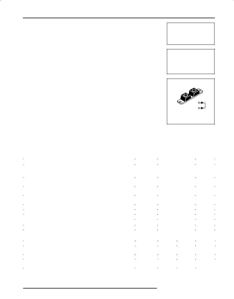
. . . employing the Schottky Barrier principle in a large area metal±to±silicon power diode. State of the art geometry features epitaxial construction with oxide passivation and metal overlay contact. Ideally suited for low voltage, high frequency switching power supplies, free wheeling diode and polarity protection diodes.
•Guardring for Stress Protection
•Matched dual die construction ± May be Paralleled for High Current Output
•High dv/dt Capability
•Very Low Forward Voltage Drop
Mechanical Characteristics:
•Case: Epoxy, Molded with Metal Heatsink Base
•Weight: 80 grams (approximately)
•Finish: All External Surfaces Corrosion Resistant
•Base Plate Torques: See procedure given in the Package Outline Section
•Top Terminal Torque: 70 in±lb max.
•Shipped 25 units per foam
•Marking: MBRP20060CT
MBRP20060CT
SCHOTTKY BARRIER
RECTIFIER
200 AMPERES
60 VOLTS
 3
3
2
CASE 357C-03
POWERTAP II
MAXIMUM RATINGS
Rating |
|
Symbol |
Value |
Unit |
||
|
|
|
|
|
|
|
Peak Repetitive Reverse Voltage |
|
VRRM |
|
60 |
Volts |
|
Working Peak Reverse Voltage |
|
VRWM |
|
|
|
|
DC Blocking Voltage |
|
VR |
|
|
|
|
Average Rectified Forward Current |
Per Leg |
IO |
100 |
Amps |
||
(At Rated VR, TC = 120°C) |
Per Package |
|
200 |
|
||
Peak Repetitive Forward Current |
Per Leg |
IFRM |
200 |
Amps |
||
(At Rated VR, Square Wave, 20 kHz, TC = 125°C) |
|
|
|
|
|
|
Non-Repetitive Peak Surge Current |
Per Package |
IFSM |
1500 |
Amps |
||
(Surge applied at rated load conditions, halfwave, single phase, 60 Hz) |
|
|
|
|
|
|
|
|
|
|
|
|
|
Storage/Operating Case Temperature |
|
Tstg, TC |
± 55 to +150 |
°C |
||
Operating Junction Temperature |
|
TJ |
± 55 to +150 |
°C |
||
Voltage Rate of Change (Rated VR, TJ = 25°C) |
|
dv/dt |
1,000 |
V/μs |
||
THERMAL CHARACTERISTICS |
|
|
|
|
|
|
|
|
|
|
|
|
|
Thermal Resistance Ð Junction±to±Case |
Per Leg |
Rtjc |
0.44 |
°C/W |
||
ELECTRICAL CHARACTERISTICS |
|
|
|
|
|
|
|
|
|
|
|
|
|
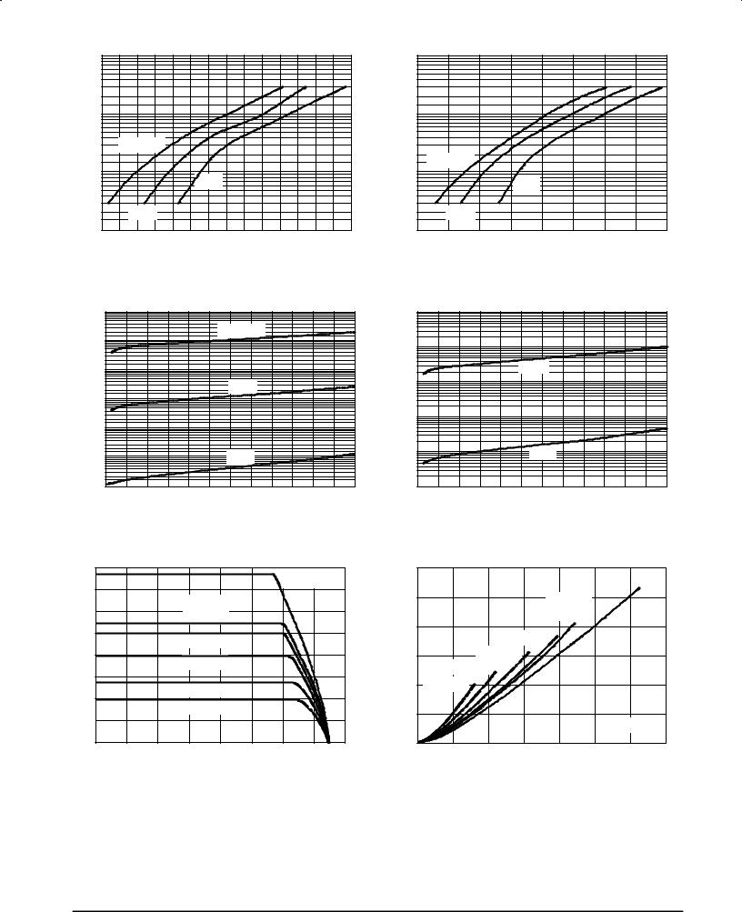
Maximum Instantaneous Forward Voltage (1), see Figure 2 |
Per Leg |
VF |
TJ = 25°C |
|
TJ = 100°C |
Volts |
(IF = 100 Amps) |
|
|
0.80 |
|
0.72 |
|
(IF = 200 Amps) |
|
|
0.92 |
|
0.82 |
|
Maximum Instantaneous Reverse Current, see Figure 4 |
Per Leg |
IR |
TJ = 25°C |
|
TJ = 100°C |
mA |
(VR = 60 V) |
|
|
0.5 |
|
100 |
|
(VR = 30 V) |
|
|
0.2 |
|
50 |
|
(1) Pulse Test: Pulse Width ≤ 250 μs, Duty Cycle ≤ 2%.
POWERTAP and SWITCHMODE are trademarks of Motorola, Inc.
Motorola, Inc. 1995
MBRP20060CT |
|
|
|
|
|
|||
CURRENT (AMPS) |
1000 |
|
|
|
|
|
|
|
100 |
|
|
|
|
|
|
|
|
FORWARD |
|
|
|
|
|
|
|
|
|
TJ = 150°C |
|
|
|
|
|
|
|
|
|
|
|
|
|
|
|
|
, INSTANTANEOUS |
10 |
|
|
25°C |
|
|
|
|
|
|
|
|
|
|
|
||
|
100°C |
|
|
|
|
|
|
|
1.0 |
|
|
|
|
|
|
|
|
F |
|
|
|
|
|
|
|
|
I |
0.2 |
0.3 |
0.4 |
0.5 |
0.6 |
0.7 |
0.8 |
0.9 |
|
||||||||
|
|
VF, INSTANTANEOUS FORWARD VOLTAGE (VOLTS) |
|
|||||
Figure 1. Typical Forward Voltage
|
1.0 |
|
|
|
|
|
|
(AMPS) |
0.1 |
|
|
TJ = 150°C |
|
|
|
|
|
|
|
|
|
||
|
|
|
|
|
|
|
|
CURRENT |
0.01 |
|
|
|
|
|
|
|
|
|
100°C |
|
|
|
|
, REVERSE |
|
|
|
|
|
|
|
0.001 |
|
|
|
|
|
|
|
0.0001 |
|
|
|
|
|
|
|
R |
|
|
|
|
|
|
|
I |
|
|
|
|
|
|
|
0.00001 |
|
|
25°C |
|
|
|
|
0.000001 |
10 |
20 |
30 |
40 |
50 |
60 |
|
|
0 |
||||||
VR, REVERSE VOLTAGE (VOLTS)
Figure 3. Typical Reverse Current
CURRENT(AMPS) |
1000 |
|
|
|
|
|
|
|
|
100 |
|
|
|
|
|
|
|
|
|
FORWARD |
|
|
|
|
|
|
|
|
|
|
TJ = 150°C |
|
|
|
|
|
|
|
|
, INSTANTANEOUS |
10 |
|
|
|
|
|
|
|
|
|
|
|
25°C |
|
|
|
|
||
|
|
|
|
|
|
|
|
||
|
100°C |
|
|
|
|
|
|
|
|
1.0 |
|
|
|
|
|
|
|
|
|
F |
|
|
0.5 |
0.6 |
0.7 |
0.8 |
|
|
|
I |
0.2 |
0.3 |
0.4 |
0.9 |
1.0 |
||||
|
|||||||||
|
VF, MAXIMUM INSTANTANEOUS FORWARD VOLTAGE (VOLTS) |
|
|||||||
Figure 2. Maximum Forward Voltage
(AMPS) |
1.0 |
|
|
|
|
|
|
|
|
|
|
|
|
|
|
CURRENT |
0.1 |
|
|
|
|
|
|
|
|
|
100°C |
|
|
|
|
0.01 |
|
|
|
|
|
|
|
REVERSE |
|
|
|
|
|
|
|
0.001 |
|
|
|
|
|
|
|
, MAXIMUM |
0.0001 |
|
|
° |
|
|
|
|
|
|
25 C |
|
|
|
|
|
|
|
|
|
|
|
|
R |
|
|
|
|
|
|
|
I |
|
|
|
|
|
|
|
|
0.00001 |
10 |
20 |
30 |
40 |
50 |
60 |
|
0 |
VR, REVERSE VOLTAGE (VOLTS)
Figure 4. Maximum Reverse Current
(AMPS) |
160 |
|
|
dc |
|
|
FREQ = 20 kHz |
||
140 |
|
|
|
|
|||||
|
|
|
|
|
|
|
|
||
CURRENT |
120 |
|
|
SQUARE |
|
|
|
|
|
|
|
WAVE |
|
|
|
|
|
||
|
|
|
|
|
|
|
|
||
100 |
|
|
Ipk/Io = p |
|
|
|
|
||
FORWARD |
|
|
|
|
|
|
|
||
80 |
|
|
Ipk/Io = 5 |
|
|
|
|
||
|
|
|
|
|
|
|
|||
60 |
|
|
|
|
|
|
|
|
|
, AVERAGE |
|
|
|
|
|
|
|
|
|
40 |
|
|
Ipk/Io = 10 |
|
|
|
|
||
|
|
Ipk/Io = 20 |
|
|
|
|
|||
|
|
|
|
|
|
|
|||
20 |
|
|
|
|
|
|
|
|
|
O |
|
|
|
|
|
|
|
|
|
|
|
|
|
|
|
|
|
|
|
I |
|
|
|
|
|
|
|
|
|
|
0 |
20 |
40 |
60 |
80 |
100 |
120 |
140 |
160 |
|
0 |
||||||||
|
|
|
|
TC, CASE TEMPERATURE (°C) |
|
|
|||
Figure 5. Current Derating
(PER LEG)
(WATTS) |
120 |
|
|
|
|
|
dc |
|
|
|
|
|
|
|
|
||
100 |
|
|
|
|
|
|
|
|
DISSIPATION |
|
|
|
SQUARE |
|
|
|
|
|
|
|
|
|
|
|
||
|
|
|
|
WAVE |
|
|
|
|
80 |
|
|
Ipk/Io = p |
|
|
|
|
|
|
|
|
|
|
|
|
||
|
|
|
|
|
|
|
|
|
POWER |
60 |
|
Ipk/Io = 5 |
|
|
|
|
|
Ipk/Io = 10 |
|
|
|
|
|
|||
|
|
|
|
|
|
|||
|
|
|
|
|
|
|
|
|
AVERAGE |
40 |
Ipk/Io = 20 |
|
|
|
|
|
|
20 |
|
|
|
|
|
|
|
|
, |
|
|
|
|
|
|
TJ = 150°C |
|
FO |
|
|
|
|
|
|
|
|
P |
0 |
|
|
|
|
|
|
|
|
25 |
50 |
75 |
100 |
125 |
150 |
175 |
|
|
0 |
|||||||
|
|
|
IO, AVERAGE FORWARD CURRENT (AMPS) |
|
||||
Figure 6. Forward Power Dissipation
(PER LEG)
2 |
Motorola Schottky Power Rectifier Data |
C, CAPACITANCE (pF)
MBRP20060CT
10,000
TJ = 25°C
1,000
100 |
10 |
100 |
1.0 |
VR, REVERSE VOLTAGE (VOLTS)
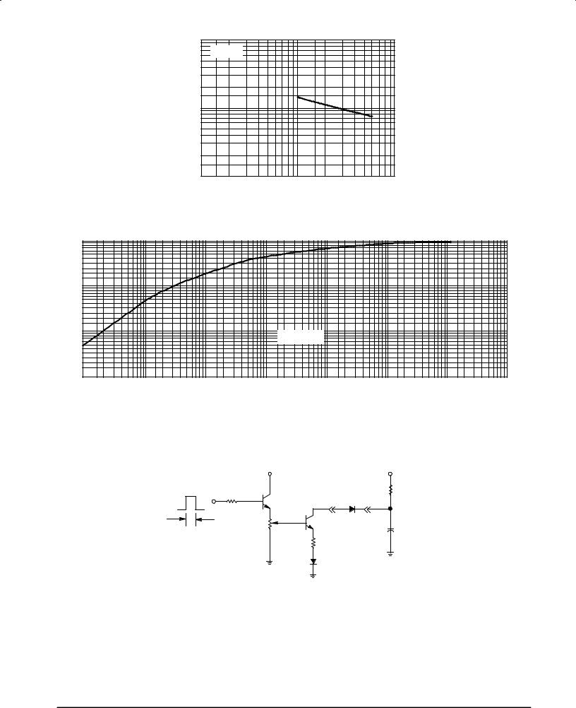
Figure 7. Capacitance
(NORMALIZED) |
1.0 |
|
|
|
|
|
|
|
|
|
|
|
|
|
|
|
|
||
RESISTANCE |
0.1 |
|
|
|
|
|
|
|
|
|
|
|
|
|
|
|
|
||
THERMAL |
0.01 |
|
|
|
Rtjc(t) = Rtjc*r(t) |
|
|
|
|
|
|
|
|
|
|
|
|||
TRANSIENT |
0.001 |
|
|
|
|
|
|
|
|
, |
0.00001 |
0.0001 |
0.001 |
0.01 |
0.1 |
1.0 |
10 |
100 |
|
(T) |
|||||||||
|
|
|
|
|
|
|
|
||
R |
|
|
|
|
T, TIME (s) |
|
|
|
|
|
|
|
|
|
|
|
|
Figure 8. Thermal Response
|
VCC |
|
+ 150 V, |
|
|
12 Vdc |
|
10 mAdc |
|
12 V |
100 |
|
|
2 kW |
2N2222 |
D.U.T. |
|
||
|
|
|
||
2 ms |
CURRENT |
|
2N6277 |
|
1 kHz |
|
+ |
||
|
AMPLITUDE |
100 W |
|
4 mF |
|
ADJUST |
CARBON |
1 CARBON |
|
|
0 ±10 AMPS |
|
|
|
|
|
|
|
|
|
|
|
1N5817 |
|
Figure 9. Test Circuit for Repetitive
Reverse Current
Motorola Schottky Power Rectifier Data |
3 |
MBRP20060CT
MAXIMUM MECHANICAL RATINGS
Terminal Penetration: |
0.235 max |
|
|
Terminal Torque: |
70 in-lb max |
|
|
Mounting Torque Ð |
|
Outside Holes: |
70 in-lb max |
|
|
Mounting Torque Ð |
|
Center Hole: |
8±10 in-lb max |
|
|
Seating Plane |
1 mil per in. |
Flatness |
(between mounting holes) |
|
|
POWERTAP MECHANICAL DATA
APPLIES OVER OPERATING TEMPERATURE
2″ |
Vertical Pull |
2 in. Lever Pull |
250 lbs. max |
50 lbs. max |
Note: While the POWERTAP is capable of sustaining these vertical and levered tensions, the intimate contact
Note: between POWERTAP and heat sink may be lost. This could lead to thermal runaway. The use of very
Note: flexible leads is recommended for the anode connections. Use of thermal grease is highly recommended.
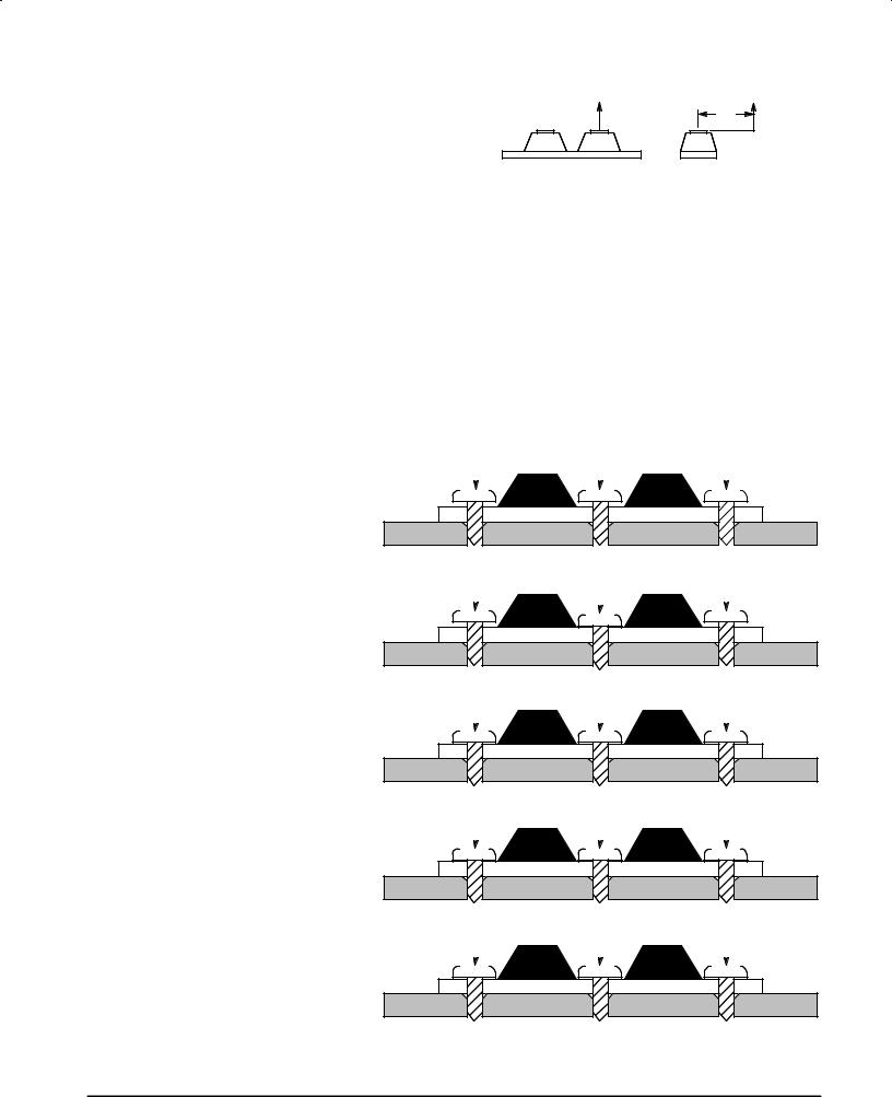
MOUNTING PROCEDURE
The POWERTAP package requires special mounting considerations because of the long longitudinal axis of the copper heat sink. It is important to follow the proper tightening sequence to avoid warping the heat sink, which can reduce thermal contact between the POWERTAP and heat sink.
STEP 1:
Locate the POWERTAP on the heat sink and start mounting bolts into the threads by hand (2 or 3 turns).
2 ± 3 TURNS |
|
|
|
2 ± 3 TURNS |
|
|
|
2 ± 3 TURNS |
|||||||||
|
|
|
|
|
|
|
|
|
|
|
|
|
|
|
|
|
|
POWER |
TAP |
HEAT |
SINK |
STEP 2:
Finger tighten the center bolt. The bolt may catch on the threads of the heat sink so it is important to make sure the face of the bolt or washer is in contact with the surface of the POWERTAP.
STEP 3:
Tighten each of the end bolts between 5 to 10 in-lb.
STEP 4:
Tighten the center bolt between 8 to 10 in-lb.
STEP 5:
Finally, tighten the end bolts to 70 in-lb.
2 ± 3 TURNS |
|
|
|
FINGER-TIGHT |
|
|
|
2 ± 3 TURNS |
|||||||||
|
|
|
|
|
|
|
|
|
|
|
|
|
|
|
|
|
|
|
|
|
|
|
|
|
|
|
|
|
|
|
|
|
|
|
|
POWER |
TAP |
HEAT |
SINK |
5 ± 10 IN-LB |
|
|
|
FINGER-TIGHT |
|
|
|
5 ± 10 IN-LB |
|||||||||
|
|
|
|
|
|
|
|
|
|
|
|
|
|
|
|
|
|
POWER |
TAP |
HEAT |
SINK |
5 ± 10 IN-LB |
|
|
|
8 ± 10 IN-LB |
|
|
|
5 ± 10 IN-LB |
|||||||||
|
|
|
|
|
|
|
|
|
|
|
|
|
|
|
|
|
|
POWER |
TAP |
HEAT |
SINK |
70 IN-LB |
|
|
|
8 ± 10 IN-LB |
|
|
|
70 IN-LB |
|||||||||
|
|
|
|
|
|
|
|
|
|
|
|
|
|
|
|
|
|
POWER |
TAP |
HEAT |
SINK |
4 |
Motorola Schottky Power Rectifier Data |
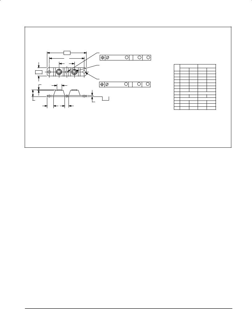
MBRP20060CT
PACKAGE DIMENSIONS
|
-A- |
W |
|
|
|
|
|
|
NOTES: |
|
|
|
|
|
|
|
|
|
|
|
|
1. DIMENSIONING AND TOLERANCING PER ANSI |
|||||||
|
R |
|
0.25 (0.010) M |
T |
A |
M |
B |
M |
|
Y14.5M, 1982. |
|
|
|
|
|
|
2. |
CONTROLLING DIMENSION: INCH. |
|
||||||||||
|
G |
|
|
|
|
|
|
|
3. TERMINAL PENETRATION: 5.97 (0.235) MAXIMUM. |
|||||
|
N |
|
|
|
|
|
|
|
|
INCHES |
MILLIMETERS |
|||
|
|
|
|
|
|
|
|
|
|
|||||
|
|
|
|
|
|
|
|
|
|
|
||||
-B- |
|
|
|
|
|
|
|
|
|
DIM |
MIN |
MAX |
MIN |
MAX |
|
|
|
|
|
|
|
|
|
A |
3.450 |
3.635 |
87.63 |
92.33 |
|
|
|
|
|
|
|
|
|
|
|
B |
0.700 |
0.810 |
17.78 |
20.57 |
|
|
Q 2 PL |
|
|
|
|
|
|
C |
0.615 |
0.640 |
15.53 |
16.26 |
|
|
|
|
0.25 (0.010) M |
T |
A |
M |
B |
M |
|
E |
0.120 |
0.130 |
3.05 |
3.30 |
H |
F |
|
|
F |
0.435 |
0.445 |
11.05 |
11.30 |
||||||
|
|
|
|
|
|
|
|
|
|
G |
1.370 |
1.380 |
34.80 |
35.05 |
|
|
|
|
|
|
|
|
|
|
H |
0.007 |
0.030 |
0.18 |
0.76 |
|
|
|
|
|
|
|
|
|
|
N |
1/4±20UNC 2B |
1/4±20UNC 2B |
||
|
|
-T- |
SEATING |
|
|
|
|
|
|
Q |
0.270 |
0.285 |
6.86 |
7.32 |
C |
|
|
|
|
|
|
|
R |
31.50 BSC |
80.01 BSC |
||||
|
PLANE |
|
|
|
|
|
|
|||||||
|
E |
|
|
|
|
|
|
U |
0.600 |
0.630 |
15.24 |
16.00 |
||
|
|
|
|
|
|
|
|
|
||||||
U |
V |
|
|
|
|
|
|
|
|
V |
0.330 |
0.375 |
8.39 |
9.52 |
|
|
|
|
|
|
|
|
|
|
W |
0.170 |
0.190 |
4.32 |
4.82 |
CASE 357C±03
ISSUE C
Motorola Schottky Power Rectifier Data |
5 |