Материал: 892051
 AT89C2051
Features
∙Compatible with MCS-51™ Products
∙2 Kbytes of Reprogrammable Flash Memory Endurance: 1,000 Write/Erase Cycles
∙2.7 V to 6 V Operating Range
∙Fully Static Operation: 0 Hz to 24 MHz
∙Two-Level Program Memory Lock
∙128 x 8-Bit Internal RAM
∙15 Programmable I/O Lines
∙Two 16-Bit Timer/Counters
∙Six Interrupt Sources
∙Programmable Serial UART Channel
∙Direct LED Drive Outputs
∙On-Chip Analog Comparator
∙Low Power Idle and Power Down Modes
Description
The AT89C2051 is a low-voltage, high-performance CMOS 8-bit microcomputer with 2 Kbytes of Flash programmable and erasable read only memory (PEROM). The device is manufactured using Atmel’s high density nonvolatile memory technology and is compatible with the industry standard MCS-51™ instruction set and pinout. By combining a versatile 8-bit CPU with Flash on a monolithic chip, the Atmel AT89C2051 is a powerful microcomputer which provides a highly flexible and cost effective solution to many embedded control applications.
The AT89C2051 provides the following standard features: 2 Kbytes of Flash, 128 bytes of RAM, 15 I/O lines, two 16-bit timer/counters, a five vector two-level interrupt architecture, a full duplex serial port, a precision analog comparator, on-chip oscillator and clock circuitry. In addition, the AT89C2051 is designed with static logic for operation down to zero frequency and supports two software selectable power saving modes. The Idle Mode stops the CPU while allowing the RAM, timer/counters, serial port and interrupt system to continue functioning. The Power Down Mode saves the RAM contents but freezes the oscillator disabling all other chip functions until the next hardware reset.
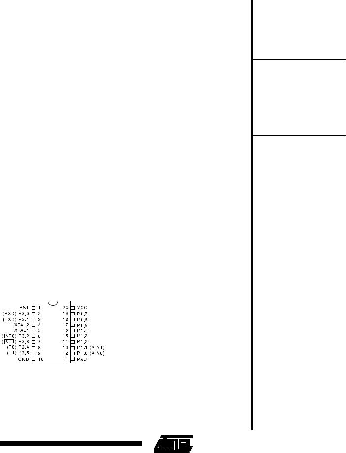
Pin Configuration
PDIP/SOIC
8-Bit Microcontroller with 2 Kbytes Flash
0368C
3-17
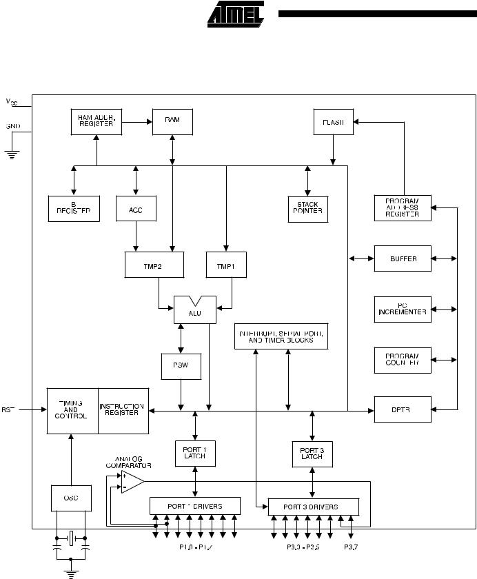
Block Diagram
3-18 |
AT89C2051 |
|
|
Pin Description
VCC
Supply voltage.
GND
Ground.
Port 1
Port 1 is an 8-bit bidirectional I/O port. Port pins P1.2 to P1.7 provide internal pullups. P1.0 and P1.1 require external pullups. P1.0 and P1.1 also serve as the positive input (AIN0) and the negative input (AIN1), respectively, of the on-chip precision analog comparator. The Port 1 output buffers can sink 20 mA and can drive LED displays directly. When 1s are written to Port 1 pins, they can be used as inputs. When pins P1.2 to P1.7 are used as inputs and are externally pulled low, they will source current (IIL) because of the internal pullups.
Port 1 also receives code data during Flash programming and program verification.
Port 3
Port 3 pins P3.0 to P3.5, P3.7 are seven bidirectional I/O pins with internal pullups. P3.6 is hard-wired as an input to the output of the on-chip comparator and is not accessible as a general purpose I/O pin. The Port 3 output buffers can sink 20 mA. When 1s are written to Port 3 pins they are pulled high by the internal pullups and can be used as inputs. As inputs, Port 3 pins that are externally being pulled low will source current (IIL) because of the pullups.
Port 3 also serves the functions of various special features of the AT89C2051 as listed below:
Port Pin |
|
Alternate Functions |
|
P3.0 |
|
RXD (serial input port) |
|
P3.1 |
|
TXD (serial output port) |
|
|
|
|
|
P3.2 |
|
INT0 (external interrupt 0) |
|
|
|
|
|
P3.3 |
|
INT1 (external interrupt 1) |
|
P3.4 |
|
T0 (timer 0 external input) |
|
P3.5 |
|
T1 (timer 1 external input) |
|
Port 3 also receives some control signals for Flash programming and programming verification.
RST
Reset input. All I/O pins are reset to 1s as soon as RST goes high. Holding the RST pin high for two machine cycles while the oscillator is running resets the device.
Each machine cycle takes 12 oscillator or clock cycles.
XTAL1
Input to the inverting oscillator amplifier and input to the internal clock operating circuit.
XTAL2
Output from the inverting oscillator amplifier.
AT89C2051
Oscillator Characteristics
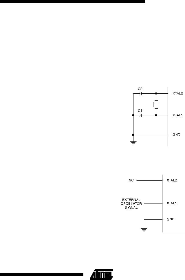
XTAL1 and XTAL2 are the input and output, respectively, of an inverting amplifier which can be configured for use as an on-chip oscillator, as shown in Figure 1. Either a quartz crystal or ceramic resonator may be used. To drive the device from an external clock source, XTAL2 should be left unconnected while XTAL1 is driven as shown in Figure 2. There are no requirements on the duty cycle of the external clock signal, since the input to the internal clocking circuitry is through a divide-by-two flip-flop, but minimum and maximum voltage high and low time specifications must be observed.
Figure 1. Oscillator Connections
Notes: C1, C2 = 30 pF ± 10 pF for Crystals
= 40 pF ± 10 pF for Ceramic Resonators
Figure 2. External Clock Drive Configuration
3-19

Special Function Registers
A map of the on-chip memory area called the Special Function Register (SFR) space is shown in the table below.
Note that not all of the addresses are occupied, and unoccupied addresses may not be implemented on the chip. Read accesses to these addresses will in general return
random data, and write accesses will have an indeterminate effect.
User software should not write 1s to these unlisted locations, since they may be used in future products to invoke new features. In that case, the reset or inactive values of the new bits will always be 0.
Table 1. AT89C2051 SFR Map and Reset Values |
|
|
|
|
||||
0F8H |
|
|
|
|
|
|
|
|
|
|
|
|
|
|
|
|
|
0F0H |
B |
|
|
|
|
|
|
|
00000000 |
|
|
|
|
|
|
|
|
|
|
|
|
|
|
|
|
|
0E8H |
|
|
|
|
|
|
|
|
|
|
|
|
|
|
|
|
|
|
|
|
|
|
|
|
|
|
0E0H |
ACC |
|
|
|
|
|
|
|
00000000 |
|
|
|
|
|
|
|
|
|
|
|
|
|
|
|
|
|
0D8H |
|
|
|
|
|
|
|
|
|
|
|
|
|
|
|
|
|
|
|
|
|
|
|
|
|
|
0D0H |
PSW |
|
|
|
|
|
|
|
00000000 |
|
|
|
|
|
|
|
|
|
|
|
|
|
|
|
|
|
0C8H |
|
|
|
|
|
|
|
|
|
|
|
|
|
|
|
|
|
0C0H |
|
|
|
|
|
|
|
|
|
|
|
|
|
|
|
|
|
|
|
|
|
|
|
|
|
|
0B8H |
IP |
|
|
|
|
|
|
|
XXX00000 |
|
|
|
|
|
|
|
|
|
|
|
|
|
|
|
|
|
|
|
|
|
|
|
|
|
|
0B0H |
P3 |
|
|
|
|
|
|
|
11111111 |
|
|
|
|
|
|
|
|
|
|
|
|
|
|
|
|
|
|
|
|
|
|
|
|
|
|
0A8H |
IE |
|
|
|
|
|
|
|
0XX00000 |
|
|
|
|
|
|
|
|
|
|
|
|
|
|
|
|
|
0A0H |
|
|
|
|
|
|
|
|
|
|
|
|
|
|
|
|
|
|
|
|
|
|
|
|
|
|
98H |
SCON |
SBUF |
|
|
|
|
|
|
00000000 |
XXXXXXXX |
|
|
|
|
|
|
|
|
|
|
|
|
|
|
||
|
|
|
|
|
|
|
|
|
90H |
P1 |
|
|
|
|
|
|
|
11111111 |
|
|
|
|
|
|
|
|
|
|
|
|
|
|
|
|
|
|
|
|
|
|
|
|
|
|
88H |
TCON |
TMOD |
TL0 |
TL1 |
TH0 |
TH1 |
|
|
00000000 |
00000000 |
00000000 |
00000000 |
00000000 |
00000000 |
|
|
|
|
|
|
||||||
|
|
|
|
|
|
|
|
|
80H |
|
SP |
DPL |
DPH |
|
|
|
PCON |
|
00000111 |
00000000 |
00000000 |
|
|
|
0XXX0000 |
|
|
|
|
|
|
||||
|
|
|
|
|
|
|
|
|
0FFH
0F7H
0EFH
0E7H
0DFH
0D7H
0CFH
0C7H
0BFH
0B7H
0AFH
0A7H
9FH
97H
8FH
87H
3-20 |
AT89C2051 |
|
|

Restrictions on Certain Instructions
The AT89C2051 and is an economical and cost-effective member of Atmel’s growing family of microcontrollers. It contains 2 Kbytes of flash program memory. It is fully compatible with the MCS-51 architecture, and can be programmed using the MCS-51 instruction set. However, there are a few considerations one must keep in mind when utilizing certain instructions to program this device.
All the instructions related to jumping or branching should be restricted such that the destination address falls within the physical program memory space of the device, which is 2K for the AT89C2051. This should be the responsibility of the software programmer. For example, LJMP 7E0H would be a valid instruction for the AT89C2051 (with 2K of memory), whereas LJMP 900H would not.
1. Branching instructions:
LCALL, LJMP, ACALL, AJMP, SJMP, JMP @A+DPTR
These unconditional branching instructions will execute correctly as long as the programmer keeps in mind that the destination branching address must fall within the physical boundaries of the program memory size (locations 00H to 7FFH for the 89C2051). Violating the physical space limits may cause unknown program behavior.
CJNE [...], DJNZ [...], JB, JNB, JC, JNC, JBC, JZ, JNZ With these conditional branching instructions the same rule above applies. Again, violating the memory boundaries may cause erratic execution.
AT89C2051
For applications involving interrupts the normal interrupt service routine address locations of the 80C51 family architecture have been preserved.
2. MOVX-related instructions, Data Memory:
The AT89C2051 contains 128 bytes of internal data memory. Thus, in the AT89C2051 the stack depth is limited to 128 bytes, the amount of available RAM. External DATA memory access is not supported in this device, nor is external PROGRAM memory execution. Therefore, no MOVX [...] instructions should be included in the program.
A typical 80C51 assembler will still assemble instructions, even if they are written in violation of the restrictions mentioned above. It is the responsibility of the controller user to know the physical features and limitations of the device being used and adjust the instructions used correspondingly.
3-21