Материал: 892051

Program Memory Lock Bits
On the chip are two lock bits which can be left unprogrammed (U) or can be programmed (P) to obtain the additional features listed in the table below:
Lock Bit Protection Modes(1)
Program Lock Bits |
|
|||
|
LB1 |
LB2 |
Protection Type |
|
|
|
|
|
|
1 |
U |
U |
No program lock features. |
|
2 |
P |
U |
Further programming of the |
|
Flash is disabled. |
||||
|
|
|
||
3 |
P |
P |
Same as mode 2, also verify |
|
is disabled. |
||||
|
|
|
||
Note: 1. The Lock Bits can only be erased with the Chip Erase operation
Idle Mode
In idle mode, the CPU puts itself to sleep while all the onchip peripherals remain active. The mode is invoked by software. The content of the on-chip RAM and all the special functions registers remain unchanged during this mode. The idle mode can be terminated by any enabled interrupt or by a hardware reset.
P1.0 and P1.1 should be set to ’0’ if no external pullups are used, or set to ’1’ if external pullups are used.
It should be noted that when idle is terminated by a hardware reset, the device normally resumes program execution, from where it left off, up to two machine cycles before the internal reset algorithm takes control. On-chip hardware inhibits access to internal RAM in this event, but access to the port pins is not inhibited. To eliminate the possibility of an unexpected write to a port pin when Idle is terminated by reset, the instruction following the one that invokes Idle should not be one that writes to a port pin or to external memory.
Power Down Mode
In the power down mode the oscillator is stopped, and the instruction that invokes power down is the last instruction executed. The on-chip RAM and Special Function Registers retain their values until the power down mode is terminated. The only exit from power down is a hardware reset. Reset redefines the SFRs but does not change the onchip RAM. The reset should not be activated before VCC is restored to its normal operating level and must be held active long enough to allow the oscillator to restart and stabilize.
P1.0 and P1.1 should be set to ’0’ if no external pullups are used, or set to ’1’ if external pullups are used.
3-22 AT89C2051
Programming The Flash
The AT89C2051 is shipped with the 2 Kbytes of on-chip PEROM code memory array in the erased state (i.e., contents = FFH) and ready to be programmed. The code memory array is programmed one byte at a time. Once the array is programmed, to re-program any non-blank byte, the entire memory array needs to be erased electrically.
Internal Address Counter: The AT89C2051 contains an internal PEROM address counter which is always reset to 000H on the rising edge of RST and is advanced by applying a positive going pulse to pin XTAL1.
Programming Algorithm: To program the AT89C2051, the following sequence is recommended.
1.Power-up sequence:
Apply power between VCC and GND pins Set RST and XTAL1 to GND
With all other pins floating, wait for greater than 10 milliseconds
2.Set pin RST to ’H’ Set pin P3.2 to ’H’
3.Apply the appropriate combination of ’H’ or ’L’ logic levels to pins P3.3, P3.4, P3.5, P3.7 to select one of the programming operations shown in the PEROM Programming Modes table.
To Program and Verify the Array:
4.Apply data for Code byte at location 000H to P1.0 to P1.7.
5.Raise RST to 12V to enable programming.
6.Pulse P3.2 once to program a byte in the PEROM array or the lock bits. The byte-write cycle is self-timed and typically takes 1.2 ms.
7.To verify the programmed data, lower RST from 12V to logic ’H’ level and set pins P3.3 to P3.7 to the appropiate levels. Output data can be read at the port P1 pins.
8.To program a byte at the next address location, pulse XTAL1 pin once to advance the internal address counter. Apply new data to the port P1 pins.
9.Repeat steps 5 through 8, changing data and advancing the address counter for the entire 2 Kbytes array or until the end of the object file is reached.
10.Power-off sequence: set XTAL1 to ’L’
set RST to ’L’
Float all other I/O pins Turn Vcc power off

Data Polling: The AT89C2051 features Data Polling to indicate the end of a write cycle. During a write cycle, an attempted read of the last byte written will result in the complement of the written data on P1.7. Once the write cycle has been completed, true data is valid on all outputs, and the next cycle may begin. Data Polling may begin any time after a write cycle has been initiated.
Ready/Busy: The Progress of byte programming can also be monitored by the RDY/BSY output signal. Pin P3.1 is pulled low after P3.2 goes High during programming to indicate BUSY. P3.1 is pulled High again when programming is done to indicate READY.
Program Verify: If lock bits LB1 and LB2 have not been programmed code data can be read back via the data lines for verification:
1.Reset the internal address counter to 000H by bringing RST from ’L’ to ’H’.
2.Apply the appropriate control signals for Read Code data and read the output data at the port P1 pins.
3.Pulse pin XTAL1 once to advance the internal address counter.
4.Read the next code data byte at the port P1 pins.
5.Repeat steps 3 and 4 until the entire array is read.
The lock bits cannot be verified directly. Verification of the lock bits is achieved by observing that their features are enabled.
AT89C2051
Chip Erase: The entire PEROM array (2 Kbytes) and the two Lock Bits are erased electrically by using the proper combination of control signals and by holding P3.2 low for 10 ms. The code array is written with all “1"s in the Chip Erase operation and must be executed before any nonblank memory byte can be re-programmed.
Reading the Signature Bytes: The signature bytes are read by the same procedure as a normal verification of locations 000H, 001H, and 002H, except that P3.5 and P3.7 must be pulled to a logic low. The values returned are as follows.
(000H) = 1EH indicates manufactured by Atmel
(001H) = 21H indicates 89C2051
Programming Interface
Every code byte in the Flash array can be written and the entire array can be erased by using the appropriate combination of control signals. The write operation cycle is self-timed and once initiated, will automatically time itself to completion.
All major programming vendors offer worldwide support for the Atmel microcontroller series. Please contact your local programming vendor for the appropriate software revision.
Flash Programming Modes
|
|
|
P3.2/ |
|
|
|
|
|
Mode |
|
RST |
|
P3.3 |
P3.4 |
P3.5 |
P3.7 |
|
|
PROG |
|
||||||
Write Code Data(1,3) |
|
12V |
|
|
L |
H |
H |
H |
|
|
|
|
|
|
|
|
|
Read Code Data(1) |
|
H |
H |
L |
L |
H |
H |
|
Write Lock |
Bit - 1 |
12V |
|
|
H |
H |
H |
H |
|
Bit - 2 |
12V |
|
|
H |
H |
L |
L |
|
|
|
|
|
|
|
|
|
Chip Erase |
|
12V |
(2) |
H |
L |
L |
L |
|
|
|
|
||||||
|
|
|
|
|
|
|
|
|
Read Signature Byte |
|
H |
H |
L |
L |
L |
L |
|
|
|
|
|
|
|
|
|
|
Notes: 1. The internal PEROM address counter is reset to 000H |
2. |
Chip Erase requires a 10 ms PROG pulse. |
on the rising edge of RST and is advanced by a posi- |
3. |
P3.1 is pulled Low during programming to indicate |
tive pulse at XTAL1 pin. |
|
RDY/BSY\. |
3-23
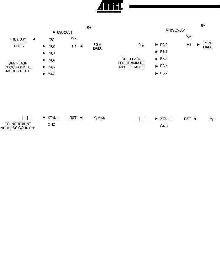
Figure 3. Programming the Flash Memory |
|
|
|
|
|
|
Figure 4. Verifying the Flash Memory |
|
|
|
|
|
|
|||||||||||||||||||||||||||||
|
|
|
|
|
|
|
|
|
|
|
|
|
|
|
|
|
|
|
|
|
|
|
|
|
|
|
|
|
|
|
|
|
|
|
|
|
|
|
|
|
|
|
|
|
|
|
|
|
|
|
|
|
|
|
|
|
|
|
|
|
|
|
|
|
|
|
|
|
|
|
|
|
|
|
|
|
|
|
|
|
|
|
|
|
|
|
|
|
|
|
|
|
|
|
|
|
|
|
|
|
|
|
|
|
|
|
|
|
|
|
|
|
|
|
|
|
|
|
|
|
|
|
|
|
|
|
|
|
|
|
|
|
|
|
|
|
|
|
|
|
|
|
|
|
|
|
|
|
|
|
|
|
|
|
|
|
|
|
|
|
|
|
|
|
|
|
|
|
|
|
|
|
|
|
|
|
|
|
|
|
|
|
|
|
|
|
|
|
|
|
|
|
|
|
|
|
|
|
|
|
|
|
|
|
|
|
|
|
|
|
|
|
|
|
|
|
|
|
|
|
|
|
|
|
|
|
|
|
|
|
|
|
|
|
|
|
|
|
|
|
|
|
|
|
|
|
|
|
|
|
|
|
|
|
|
|
|
|
|
|
|
|
|
|
|
|
|
|
|
|
|
|
|
|
|
|
|
|
|
|
|
|
|
|
|
|
|
|
|
|
|
|
|
|
|
|
|
|
|
|
|
|
|
|
|
|
|
|
|
|
|
|
|
|
|
|
|
|
|
|
|
|
|
|
|
|
|
|
|
|
|
|
|
|
|
|
|
|
|
|
|
|
|
|
|
|
|
|
|
|
|
|
|
|
|
|
|
|
|
|
|
|
|
|
|
|
|
|
|
|
|
|
|
|
|
|
|
|
|
|
|
|
|
|
|
|
|
|
|
|
|
|
|
|
|
|
|
|
|
|
|
|
|
|
|
|
|
|
|
|
|
|
|
|
|
|
|
|
|
|
|
|
|
|
|
|
|
|
|
|
|
|
|
|
|
|
|
|
|
|
|
|
|
|
|
|
|
|
|
|
|
|
|
|
|
|
|
|
|
|
|
|
|
|
|
|
|
|
|
|
|
|
|
|
|
|
|
|
|
|
|
|
|
|
|
|
|
|
|
|
|
|
|
|
|
|
|
|
|
|
|
|
|
|
|
|
|
|
|
|
|
|
|
|
|
|
|
|
|
|
|
|
|
|
|
|
|
|
|
|
|
|
|
|
|
|
|
|
|
|
|
|
|
|
|
|
|
|
|
|
|
|
|
|
|
|
|
|
|
|
|
|
|
|
|
|
|
|
|
|
|
|
|
|
|
|
|
|
|
|
|
|
|
|
|
|
|
|
|
|
|
|
|
|
|
|
|
|
|
|
|
|
|
|
|
|
|
|
|
|
|
|
|
|
|
|
|
|
|
|
|
|
|
|
|
|
|
|
|
|
|
|
|
|
|
|
|
|
|
|
|
|
|
|
|
|
|
|
|
|
|
|
|
|
|
|
|
|
|
|
|
|
|
|
|
|
|
|
|
|
|
|
|
|
|
|
|
|
|
|
|
|
|
|
|
|
|
|
|
|
|
|
|
|
|
|
|
|
|
|
|
|
|
|
|
|
|
|
|
|
|
|
|
|
|
|
|
|
|
|
|
|
|
|
|
|
|
|
|
|
|
|
|
|
|
|
|
|
|
|
|
|
|
|
|
|
|
|
|
|
|
|
|
|
|
|
|
|
|
|
|
|
|
|
|
|
|
|
|
|
|
|
|
|
|
|
|
|
|
|
|
|
|
|
|
|
|
|
|
|
|
|
|
|
|
|
|
|
|
|
|
|
|
|
|
|
|
|
|
|
|
|
|
|
|
|
|
|
|
|
|
|
|
|
|
|
|
|
|
|
|
|
|
|
|
|
|
|
|
|
|
|
|
|
|
|
|
|
|
|
|
|
|
|
|
|
|
|
|
|
|
|
|
|
|
|
|
|
|
|
|
|
|
|
|
|
|
|
|
|
|
|
|
|
|
|
|
|
|
|
|
|
|
|
|
|
|
|
|
|
|
|
|
|
|
|
|
|
|
|
|
|
|
|
|
|
|
|
|
|
|
|
|
|
|
|
|
|
|
|
|
|
|
|
|
|
|
|
|
|
|
|
|
|
|
|
|
|
|
|
|
|
|
|
|
|
|
|
|
|
|
|
|
|
|
|
|
|
|
|
|
|
|
|
|
|
|
|
|
|
|
|
|
|
|
|
|
|
|
|
|
|
|
|
|
|
|
|
|
|
|
|
|
|
|
|
|
|
|
|
|
|
|
|
|
|
|
|
|
|
|
|
|
|
|
|
|
|
|
|
|
|
|
|
|
|
|
|
|
|
|
|
|
|
|
|
|
|
|
|
|
|
|
|
|
|
|
|
|
|
|
|
|
|
|
|
|
|
|
|
|
|
|
|
|
|
|
|
|
|
|
|
|
|
|
|
|
|
|
|
|
|
|
|
|
|
|
|
|
|
|
|
|
|
|
|
|
|
|
|
|
|
|
|
|
|
|
Flash Programming and Verification Characteristics
TA = 21°C to 27°C, V CC = 5.0 ± 10%
Symbol |
Parameter |
Min |
Max |
Units |
||||||||||||||
VPP |
|
Programming Enable Voltage |
11.5 |
12.5 |
V |
|||||||||||||
IPP |
|
Programming Enable Current |
|
250 |
μA |
|||||||||||||
tDVGL |
|
|
|
|
|
|
|
|
|
|
|
|
|
|
|
|
|
μs |
|
Data Setup to PROG Low |
1.0 |
|
|||||||||||||||
tGHDX |
|
|
|
|
|
|
|
|
|
|
|
|
|
|
|
|
μs |
|
|
Data Hold After PROG |
1.0 |
|
|||||||||||||||
tEHSH |
|
|
|
|
|
|
|
|
|
|
|
|
|
|
μs |
|||
|
P3.4 (ENABLE) High to VPP |
1.0 |
|
|||||||||||||||
tSHGL |
|
|
|
|
|
|
|
|
|
|
|
|
|
μs |
||||
|
VPP Setup to PROG Low |
10 |
|
|||||||||||||||
tGHSL |
|
|
|
|
|
|
|
|
|
|
|
μs |
||||||
|
VPP Hold After PROG |
10 |
|
|||||||||||||||
tGLGH |
|
|
|
|
|
|
|
|
|
|
μs |
|||||||
|
PROG Width |
1 |
110 |
|||||||||||||||
tELQV |
|
|
|
|
|
|
|
|
|
μs |
||||||||
|
ENABLE Low to Data Valid |
|
1.0 |
|||||||||||||||
tEHQZ |
|
|
|
|
|
|
|
|
μs |
|||||||||
|
Data Float After ENABLE |
0 |
1.0 |
|||||||||||||||
tGHBL |
|
|
|
|
|
|
|
|
||||||||||
|
PROG High to BUSY Low |
|
50 |
ns |
||||||||||||||
tWC |
|
Byte Write Cycle Time |
|
2.0 |
ms |
|||||||||||||
tBHIH |
|
RDY/BSY\ to Increment Clock Delay |
1.0 |
|
μs |
|||||||||||||
tIHIL |
|
Increment Clock High |
200 |
|
ns |
|||||||||||||
Note: 1. Only used in 12-volt programming mode.
3-24 |
AT89C2051 |
|
|
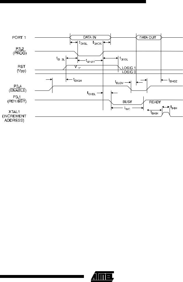
AT89C2051
Flash Programming and Verification Waveforms
Absolute Maximum Ratings*
...................Operating Temperature |
-55°C to +125°C |
|
Storage Temperature...................... |
-65°C to +150°C |
|
Voltage on Any Pin |
|
|
with Respect to Ground ................... |
-1.0 V to +7.0 |
V |
Maximum Operating Voltage ............................ |
6.6 |
V |
DC Output Current ....................................... |
25.0 mA |
|
|
|
|
*NOTICE: Stresses beyond those listed under “Absolute Maximum Ratings” may cause permanent damage to the device. This is a stress rating only and functional operation of the device at these or any other conditions beyond those indicated in the operational sections of this specification is not implied. Exposure to absolute maximum rating conditions for extended periods may affect device reliability.
3-25

D.C. Characteristics
TA = -40°C to 85°C, V CC = 2.7 V to 6.0 V (unless otherwise noted)
Symbol |
Parameter |
Condition |
|
Min |
Max |
Units |
VIL |
Input Low Voltage |
|
|
-0.5 |
0.2 VCC-0.1 |
V |
VIH |
Input High Voltage |
(Except XTAL1, RST) |
|
0.2 VCC+0.9 |
VCC+0.5 |
V |
VIH1 |
Input High Voltage |
(XTAL1, RST) |
|
0.7 VCC |
VCC+0.5 |
V |
VOL |
Output Low Voltage(1) |
IOL = 20 mA, VCC = 5 V |
|
0.5 |
V |
|
(Ports 1, 3) |
IOL = 10 mA, VCC = 2.7 V |
|
||||
|
|
|
|
|||
|
Output High Voltage |
IOH = -80 μA, VCC = 5 V ± 10% |
2.4 |
|
V |
|
VOH |
IOH = -30 μA |
|
0.75 VCC |
|
V |
|
(Ports 1, 3) |
|
|
||||
|
IOH = -12 μA |
|
0.9 VCC |
|
V |
|
|
|
|
|
|||
IIL |
Logical 0 Input Current |
VIN = 0.45 V |
|
|
-50 |
μA |
(Ports 1, 2, 3) |
|
|
||||
|
|
|
|
|
|
|
ITL |
Logical 1 to 0 Transition |
VIN = 2 V |
|
|
-750 |
μA |
Current (Ports 1, 2, 3) |
|
|
||||
|
|
|
|
|
|
|
ILI |
Input Leakage Current |
0 < VIN < VCC |
|
|
±10 |
μA |
(Port P1.0, P1.1) |
|
|
||||
|
|
|
|
|
|
|
VOS |
Comparator Input Offset |
VCC = 5 V |
|
|
20 |
mV |
Voltage |
|
|
||||
|
|
|
|
|
|
|
VCM |
Comparator Input |
|
|
0 |
VCC |
V |
Common Mode Voltage |
|
|
||||
|
|
|
|
|
|
|
RRST |
Reset Pulldown Resistor |
|
|
50 |
300 |
KΩ |
CIO |
Pin Capacitance |
Test Freq. = 1 MHz, TA = 25°C |
|
10 |
pF |
|
|
|
Active Mode, 12 MHz, VCC = 6 V/3 V |
|
15/5.5 |
mA |
|
|
Power Supply Current |
Idle Mode, 12 MHz, VCC = 6 V/3 V |
|
5/1 |
mA |
|
|
|
|
||||
ICC |
|
P1.0 & P1.1 = 0V or VCC |
|
|||
|
|
|
|
|||
|
Power Down Mode(2) |
VCC = 6 V P1.0 & P1.1 = 0V or VCC |
|
100 |
μA |
|
|
VCC = 3 V P1.0 & P1.1 = 0V or VCC |
|
20 |
μA |
||
|
|
|
||||
Notes: 1. Under steady state (non-transient) conditions, IOL |
If IOL exceeds the test condition, VOL may exceed the |
|||||
must be externally limited as follows: |
related specification. Pins are not guaranteed to sink |
|
||||
Maximum IOL per port pin:20 mA |
|
current greater than the listed test conditions. |
|
|||
Maximum total IOL for all output pins:80 mA |
2. Minimum VCC for Power Down is 2 V. |
|
||||
3-26 |
AT89C2051 |
|
|