Материал: FA3046
S E M I C O N D U C T O R
July 1995
HFA3046, HFA3096, HFA3127, HFA3128
Ultra High Frequency Transistor Array
Features |
Description |
• NPN Transistor (fT). . . . . . . . . . . . . . . . . . . . . . . . . 8GHz
• NPN Current Gain (hFE) . . . . . . . . . . . . . . . . . . . . . . . . 70
• NPN Early Voltage (V ) . . . . . . . . . . . . . . . . . . . . . . . 50V
A
• PNP Transistor (fT). . . . . . . . . . . . . . . . . . . . . . . . 5.5GHz
• PNP Current Gain (hFE) . . . . . . . . . . . . . . . . . . . . . . . . 40
• PNP Early Voltage (V ) . . . . . . . . . . . . . . . . . . . . . . . 25V
A
• Noise Figure (50Ω) at 1.0GHz . . . . . . . . . . . . . . . . 3.5dB
• Collector-to-Collector Leakage. . . . . . . . . . . . . . . .<1pA
•Complete Isolation Between Transistors
•Pin Compatible with Industry Standard 3XXX Series Arrays
Applications
•VHF/UHF Amplifiers
•VHF/UHF Mixers
•IF Converters
•Synchronous Detectors
The HFA3046, HFA3096, HFA3127 and the HFA3128 are Ultra High Frequency Transistor Arrays that are fabricated from Harris Semiconductor’s complementary bipolar UHF-1 process. Each array consists of five dielectrically isolated transistors on a common monolithic substrate. The NPN transistors exhibit a fT of 8GHz while the PNP transistors provide a fT of 5.5GHz. Both types exhibit low noise (3.5dB), making them ideal for high frequency amplifier and mixer applications.
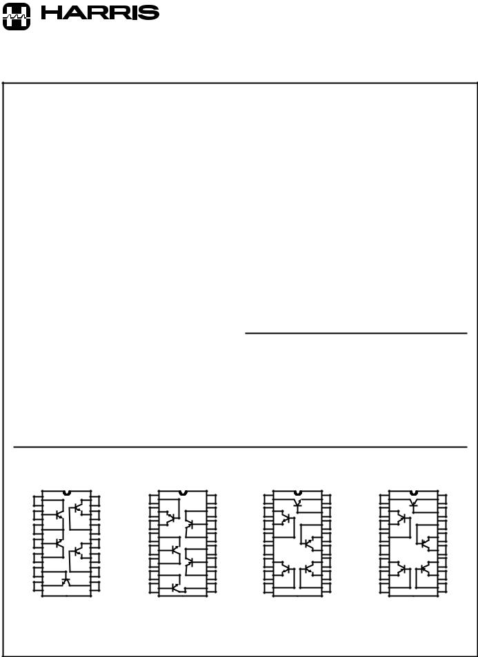
The HFA3046 and HFA3127 are all-NPN arrays while the HFA3128 has all PNP transistors. The HFA3096 is a NPNPNP combination. Access is provided to each of the terminals for the individual transistors for maximum application flexibility. Monolithic construction of these transistor arrays provides close electrical and thermal matching of the five transistors.
For PSPICE models, please request AnswerFAX document number 663046. Harris also provides an Application Note illustrating the use of these devices as RF amplifiers (request AnswerFAX document 99315).
Ordering Information
PART NUMBER |
PACKAGE |
|
|
HFA3046B |
14 Lead Plastic SOIC (N) |
|
|
HFA3096B, HFA3127B, HFA3128B |
16 Lead Plastic SOIC (N) |
|
|
HFA3046Y, HFA3096Y |
Die |
|
|
HFA3127Y, HFA3128Y |
Die |
|
|
Pinouts
HFA3046
TOP VIEW
1 |
|
14 |
2 |
Q1 |
13 |
|
||
|
|
Q5 |
3 |
|
12 |
4 |
Q2 |
11 |
|
||
5 |
|
10 |
|
|
Q4 |
6 |
|
9 |
7 |
Q3 |
8 |
|
|
HFA3096
TOP VIEW
1 |
2 |
Q1 |
|
3 |
4 |
5 |
Q2 |
6 |
7 |
Q3
8
16 NC |
15 |
Q5
14
13 |
12 |
Q4
11
10 |
9 |
HFA3127
TOP VIEW
1 |
16 |
2 |
Q1 |
15 |
|
3 |
14 |
Q2 |
Q5 |
4 |
13 |
NC |
5 |
12 |
6 |
11 |
7 |
10 |
Q3 |
Q4 |
8 |
9 |
HFA3128 |
|
TOP VIEW |
|
1 |
16 |
2 |
Q1 |
15 |
|
3 |
14 |
Q2 |
Q5 |
4 |
13 |
NC |
5 |
12 |
6 |
11 |
7 |
10 |
Q3 |
Q4 |
8 |
9 |
CAUTION: These devices are sensitive to electrostatic discharge. Users should follow proper IC Handling Procedures. |
File Number 3076.6 |
|
|
||
Copyright © Harris Corporation 1995 |
9-16 |
|
|
|
|

Specifications HFA3046, HFA3096, HFA3127, HFA3128
Absolute Maximum Ratings
Collector to Emitter Voltage (Open Base). . . . . . . . . . . . . . . . . . 8.0V Collector to Base Voltage (Shorted Base) . . . . . . . . . . . . . . . 12.0V Emitter to Base Voltage (Reverse Bias) . . . . . . . . . . . . . . . . . . 5.5V Collector Current . . . . . . . . . . . . . . . . . . . . . . . . . . . . . . . . . 15.5mA Storage Temperature Range . . . . . . . . . . . . . . . . . -65oC to +150oC
Operating Temperature Range . . . . . . . . . . . . . . . . -55oC to +125oC Junction Temperature (Die) . . . . . . . . . . . . . . . . . . . . . . . . . +175oC
Junction Temperature (Plastic Package) . . . . . . . . . . . . . . . +150oC Lead Temperature (Soldering 10s) (Lead Tips Only. . . . . . . +300oC
Thermal Information
Thermal Resistance |
θJA |
Plastic 14 Lead SOIC Package . . . . . . . . . . . . . . . . . . |
120oC/W |
Plastic 16 Lead SOIC Package . . . . . . . . . . . . . . . . . . |
115oC/W |
Maximum Package Power Dissipation at +75oC |
|
Plastic 14 Lead SOIC Package . . . . . . . . . . . . . . . . . . . |
. . . 0.63W |
Plastic 16 Lead SOIC Package . . . . . . . . . . . . . . . . . . . |
. . . 0.66W |
Any One Transistor . . . . . . . . . . . . . . . . . . . . . . . . . . . . |
. . . 0.15W |
Derating Factor Above +75oC |
8.4mW/oC |
Plastic 14 Lead SOIC Package . . . . . . . . . . . . . . . . . . . |
|
Plastic 16 Lead SOIC Package . . . . . . . . . . . . . . . . . . . |
8.7mW/oC |
CAUTION: Stresses above those listed in “Absolute Maximum Ratings” may cause permanent damage to the device. This is a stress only rating and operation of the device at these or any other conditions above those indicated in the operational sections of this specification is not implied.
Static NPN Characteristics at T = +25oC |
|
|
|
|
|
|
|
||
|
A |
|
|
|
|
|
|
|
|
|
|
|
|
|
|
|
|
|
|
|
|
|
DIE |
|
|
SOIC |
|
|
|
|
|
|
|
|
|
|
|
|
|
PARAMETERS |
TEST CONDITIONS |
MIN |
TYP |
MAX |
MIN |
TYP |
MAX |
UNITS |
|
|
|
|
|
|
|
|
|
|
|
Collector-to-Base Breakdown |
IC = 100μA, IE = 0 |
12 |
18 |
- |
12 |
18 |
- |
V |
|
Voltage, V(BR)CBO |
|
|
|
|
|
|
|
|
|
Collector-to-Emitter Break- |
IC = 100μA, IB = 0 |
8 |
12 |
- |
8 |
12 |
- |
V |
|
down Voltage, V(BR)CEO |
|
|
|
|
|
|
|
|
|
Collector-to-Emitter Break- |
IC = 100μA, Base Shorted to |
10 |
20 |
- |
10 |
20 |
- |
V |
|
down Voltage, V(BR)CES |
Emitter |
|
|
|
|
|
|
|
|
Emitter-to-Base Breakdown |
IE = 10μA, IC = 0 |
5.5 |
6 |
- |
5.5 |
6 |
- |
V |
|
Voltage, V(BR)EBO |
|
|
|
|
|
|
|
|
|
Collector-Cutoff-Current, ICEO |
VCE = 6V, IB = 0 |
- |
2 |
100 |
- |
2 |
100 |
nA |
|
Collector-Cutoff-Current, ICBO |
VCB = 8V, IE = 0 |
- |
0.1 |
10 |
- |
0.1 |
10 |
nA |
|
Collector-to-Emitter Saturation |
IC = 10mA, IB = 1mA |
- |
0.3 |
0.5 |
- |
0.3 |
0.5 |
V |
|
Voltage, VCE(SAT) |
|
|
|
|
|
|
|
|
|
Base-to-Emitter Voltage, VBE |
IC = 10mA |
- |
0.85 |
0.95 |
- |
0.85 |
0.95 |
V |
|
DC Forward-Current Transfer |
IC = 10mA |
40 |
70 |
- |
40 |
70 |
- |
|
|
Ratio, hFE |
VCE = 2V |
|
|
|
|
|
|
|
|
Early Voltage, VA |
IC = 1mA, VCE = 3.5V |
20 |
50 |
- |
20 |
50 |
- |
V |
|
Base-to-Emitter Voltage Drift |
IC = 10mA |
- |
-1.5 |
- |
- |
-1.5 |
- |
mV/oC |
|
Collector-to-Collector Leakage |
|
- |
1 |
- |
- |
1 |
- |
pA |
|
|
|
|
|
|
|
|
|
|
|
Dynamic NPN Characteristics at T = +25oC |
|
|
|
|
|
|
|
||
|
A |
|
|
|
|
|
|
|
|
|
|
|
|
|
|
|
|
|
|
|
|
|
DIE |
|
|
SOIC |
|
|
|
|
|
|
|
|
|
|
|
|
|
PARAMETERS |
TEST CONDITIONS |
MIN |
TYP |
MAX |
MIN |
TYP |
MAX |
UNITS |
|
|
|
|
|
|
|
|
|
|
|
Noise Figure |
f = 1.0GHz, VCE = 5V, |
- |
3.5 |
- |
- |
3.5 |
- |
dB |
|
|
IC = 5mA, ZS = 50Ω |
|
|
|
|
|
|
|
|
fT Current Gain-Bandwidth |
IC = 1mA, VCE = 5V |
- |
5.5 |
- |
- |
5.5 |
- |
GHz |
|
Product |
|
|
|
|
|
|
|
|
|
IC = 10mA, VCE = 5V |
- |
8 |
- |
- |
8 |
- |
GHz |
||
|
|||||||||
|
|
|
|
|
|
|
|
|
|
Power Gain-Bandwidth |
IC = 10mA, VCE = 5V |
- |
6 |
- |
- |
2.5 |
- |
GHz |
|
Product, fMAX |
|
|
|
|
|
|
|
|
|
Base-to-Emitter Capacitance |
VBE = -3V |
- |
200 |
- |
- |
500 |
- |
fF |
|
Collector-to-Base Capacitance |
VCB = 3V |
- |
200 |
- |
- |
500 |
- |
fF |
|
|
|
|
|
|
|
|
|
|
|
9-17

Specifications HFA3046, HFA3096, HFA3127, HFA3128
Static PNP Characteristics at T = +25oC |
|
|
|
|
|
|
|
|
|||
|
A |
|
|
|
|
|
|
|
|
|
|
|
|
|
|
|
|
|
|
|
|
|
|
|
|
|
|
|
DIE |
|
|
SOIC |
|
|
|
|
|
|
|
|
|
|
|
|
|||
PARAMETERS |
TEST CONDITIONS |
MIN |
TYP |
MAX |
MIN |
TYP |
MAX |
UNITS |
|||
|
|
|
|
|
|
|
|
|
|||
Collector-to-Base Breakdown |
IC = -100μA, IE = 0 |
10 |
15 |
- |
10 |
15 |
- |
V |
|||
Voltage, V(BR)CBO |
|
|
|
|
|
|
|
|
|
|
|
Collector-to-Emitter Break- |
IC = -100μA, IB = 0 |
8 |
15 |
- |
8 |
15 |
- |
V |
|||
down Voltage, V(BR)CEO |
|
|
|
|
|
|
|
|
|
|
|
Collector-to-Emitter Break- |
IC = -100μA, Base Shorted to |
10 |
15 |
- |
10 |
15 |
- |
V |
|||
down Voltage, V(BR)CES |
Emitter |
|
|
|
|
|
|
|
|
|
|
Emitter-to-Base Breakdown |
IE = -10μA, IC = 0 |
4.5 |
5 |
- |
4.5 |
5 |
- |
V |
|||
Voltage, V(BR)EBO |
|
|
|
|
|
|
|
|
|
|
|
Collector-Cutoff-Current, ICEO |
VCE = -6V, IB = 0 |
- |
2 |
100 |
- |
2 |
100 |
nA |
|||
Collector-Cutoff-Current, ICBO |
VCB = -8V, IE = 0 |
- |
0.1 |
10 |
- |
0.1 |
10 |
nA |
|||
Collector-to-Emitter Saturation |
IC = -10mA, IB = -1mA |
- |
0.3 |
0.5 |
- |
0.3 |
0.5 |
V |
|||
Voltage, VCE(SAT) |
|
|
|
|
|
|
|
|
|
|
|
Base-to-Emitter Voltage, VBE |
IC = -10mA |
|
|
- |
0.85 |
0.95 |
- |
0.85 |
0.95 |
V |
|
DC Forward-Current Transfer |
IC = -10mA, VCE = -2V |
25 |
40 |
- |
25 |
40 |
- |
|
|||
Ratio, hFE |
|
|
|
|
|
|
|
|
|
|
|
Early Voltage, VA |
IC = -1mA, VCE = -3.5V |
10 |
25 |
- |
10 |
25 |
- |
V |
|||
Base-to-Emitter Voltage Drift |
IC = -10mA |
|
|
- |
-1.5 |
- |
- |
-1.5 |
- |
mV/oC |
|
Collector-to-Collector Leakage |
|
|
|
- |
1 |
- |
- |
1 |
- |
pA |
|
|
|
|
|
|
|
|
|
|
|||
Dynamic PNP Characteristics at T = +25oC |
|
|
|
|
|
|
|
||||
|
A |
|
|
|
|
|
|
|
|
|
|
|
|
|
|
|
|
|
|
|
|
|
|
|
|
|
|
|
DIE |
|
|
SOIC |
|
|
|
|
|
|
|
|
|
|
|
|
|||
PARAMETERS |
TEST CONDITIONS |
MIN |
TYP |
MAX |
MIN |
TYP |
MAX |
UNITS |
|||
|
|
|
|
|
|
|
|
|
|||
Noise Figure |
f = 1.0GHz, VCE = -5V, |
- |
3.5 |
- |
- |
3.5 |
- |
dB |
|||
|
IC = -5mA, ZS = 50Ω |
|
|
|
|
|
|
|
|||
fT Current Gain-Bandwidth |
IC = -1mA, VCE = -5V |
- |
2 |
- |
- |
2 |
- |
GHz |
|||
Product |
|
|
|
|
|
|
|
|
|
|
|
IC = -10mA, VCE = -5V |
- |
5.5 |
- |
- |
5.5 |
- |
GHz |
||||
|
|||||||||||
Power Gain-Bandwidth |
IC = -10mA, VCE = -5V |
- |
3 |
- |
- |
2 |
- |
GHz |
|||
Product |
|
|
|
|
|
|
|
|
|
|
|
|
|
|
|
|
|
|
|
|
|
|
|
Base-to-Emitter Capacitance |
VBE = 3V |
|
|
- |
200 |
- |
- |
500 |
- |
fF |
|
|
|
|
|
|
|
|
|
|
|
|
|
Collector-to-Base Capacitance |
VCB = -3V |
|
|
- |
300 |
- |
- |
600 |
- |
fF |
|
|
|
|
|
|
|
|
|
|
|||
Differential Pair Matching Characteristics for the HFA3046 |
|
|
|
|
|
|
|||||
|
|
|
|
|
|
|
|
|
|
|
|
|
|
|
|
|
DIE |
|
|
SOIC |
|
|
|
|
|
|
|
|
|
|
|
|
|||
PARAMETERS |
TEST CONDITIONS |
MIN |
TYP |
MAX |
MIN |
TYP |
MAX |
UNITS |
|||
|
|
|
|
|
|
|
|
|
|||
Input Offset Voltage |
IC = 10mA, VCE = 5V |
- |
1.5 |
5.0 |
- |
1.5 |
5.0 |
mV |
|||
|
|
|
|
|
|
|
|
|
|||
Input Offset Current |
IC = 10mA, VCE = 5V |
- |
5 |
25 |
- |
5 |
25 |
μA |
|||
|
|
|
|
|
|
|
|
|
|
|
|
Input Offset Voltage TC |
I = 10mA, V |
CE |
= 5V |
- |
0.5 |
- |
- |
0.5 |
- |
μV/oC |
|
|
C |
|
|
|
|
|
|
|
|
||
S-Parameter and PSPICE model data is available from Harris Sales Offices.
9-18

HFA3046, HFA3096, HFA3127, HFA3128
Common Emitter S-Parameters of NPN 3μm x 50μm Transistor
FREQ. (Hz) |
|S11| |
PHASE(S11) |
|S12| |
PHASE(S12) |
|S21| |
PHASE(S21) |
|S22| |
PHASE(S22) |
|
|
|
|
|
|
|
|
|
VCE = 5V and IC = 5mA |
|
|
|
|
|
|
|
|
|
|
|
|
|
|
|
|
|
1.0E+08 |
0.83 |
-11.78 |
1.41E-02 |
78.88 |
11.07 |
168.57 |
0.97 |
-11.05 |
|
|
|
|
|
|
|
|
|
2.0E+08 |
0.79 |
-22.82 |
2.69E-02 |
68.63 |
10.51 |
157.89 |
0.93 |
-21.35 |
|
|
|
|
|
|
|
|
|
3.0E+08 |
0.73 |
-32.64 |
3.75E-02 |
59.58 |
9.75 |
148.44 |
0.86 |
-30.44 |
|
|
|
|
|
|
|
|
|
4.0E+08 |
0.67 |
-41.08 |
4.57E-02 |
51.90 |
8.91 |
140.36 |
0.79 |
-38.16 |
|
|
|
|
|
|
|
|
|
5.0E+08 |
0.61 |
-48.23 |
5.19E-02 |
45.50 |
8.10 |
133.56 |
0.73 |
-44.59 |
|
|
|
|
|
|
|
|
|
6.0E+08 |
0.55 |
-54.27 |
5.65E-02 |
40.21 |
7.35 |
127.88 |
0.67 |
-49.93 |
|
|
|
|
|
|
|
|
|
7.0E+08 |
0.50 |
-59.41 |
6.00E-02 |
35.82 |
6.69 |
123.10 |
0.62 |
-54.37 |
|
|
|
|
|
|
|
|
|
8.0E+08 |
0.46 |
-63.81 |
6.27E-02 |
32.15 |
6.11 |
119.04 |
0.57 |
-58.10 |
|
|
|
|
|
|
|
|
|
9.0E+08 |
0.42 |
-67.63 |
6.47E-02 |
29.07 |
5.61 |
115.57 |
0.53 |
-61.25 |
|
|
|
|
|
|
|
|
|
1.0E+09 |
0.39 |
-70.98 |
6.63E-02 |
26.45 |
5.17 |
112.55 |
0.50 |
-63.96 |
|
|
|
|
|
|
|
|
|
1.1E+09 |
0.36 |
-73.95 |
6.75E-02 |
24.19 |
4.79 |
109.91 |
0.47 |
-66.31 |
|
|
|
|
|
|
|
|
|
1.2E+09 |
0.34 |
-76.62 |
6.85E-02 |
22.24 |
4.45 |
107.57 |
0.45 |
-68.37 |
|
|
|
|
|
|
|
|
|
1.3E+09 |
0.32 |
-79.04 |
6.93E-02 |
20.53 |
4.15 |
105.47 |
0.43 |
-70.19 |
|
|
|
|
|
|
|
|
|
1.4E+09 |
0.30 |
-81.25 |
7.00E-02 |
19.02 |
3.89 |
103.57 |
0.41 |
-71.83 |
|
|
|
|
|
|
|
|
|
1.5E+09 |
0.28 |
-83.28 |
7.05E-02 |
17.69 |
3.66 |
101.84 |
0.40 |
-73.31 |
|
|
|
|
|
|
|
|
|
1.6E+09 |
0.27 |
-85.17 |
7.10E-02 |
16.49 |
3.45 |
100.26 |
0.39 |
-74.66 |
|
|
|
|
|
|
|
|
|
1.7E+09 |
0.25 |
-86.92 |
7.13E-02 |
15.41 |
3.27 |
98.79 |
0.38 |
-75.90 |
|
|
|
|
|
|
|
|
|
1.8E+09 |
0.24 |
-88.57 |
7.17E-02 |
14.43 |
3.10 |
97.43 |
0.37 |
-77.05 |
|
|
|
|
|
|
|
|
|
1.9E+09 |
0.23 |
-90.12 |
7.19E-02 |
13.54 |
2.94 |
96.15 |
0.36 |
-78.12 |
|
|
|
|
|
|
|
|
|
2.0E+09 |
0.22 |
-91.59 |
7.21E-02 |
12.73 |
2.80 |
94.95 |
0.35 |
-79.13 |
|
|
|
|
|
|
|
|
|
2.1E+09 |
0.21 |
-92.98 |
7.23E-02 |
11.98 |
2.68 |
93.81 |
0.35 |
-80.09 |
|
|
|
|
|
|
|
|
|
2.2E+09 |
0.20 |
-94.30 |
7.25E-02 |
11.29 |
2.56 |
92.73 |
0.34 |
-80.99 |
|
|
|
|
|
|
|
|
|
2.3E+09 |
0.20 |
-95.57 |
7.27E-02 |
10.64 |
2.45 |
91.70 |
0.34 |
-81.85 |
|
|
|
|
|
|
|
|
|
2.4E+09 |
0.19 |
-96.78 |
7.28E-02 |
10.05 |
2.35 |
90.72 |
0.33 |
-82.68 |
|
|
|
|
|
|
|
|
|
2.5E+09 |
0.18 |
-97.93 |
7.29E-02 |
9.49 |
2.26 |
89.78 |
0.33 |
-83.47 |
|
|
|
|
|
|
|
|
|
2.6E+09 |
0.18 |
-99.05 |
7.30E-02 |
8.96 |
2.18 |
88.87 |
0.33 |
-84.23 |
|
|
|
|
|
|
|
|
|
2.7E+09 |
0.17 |
-100.12 |
7.31E-02 |
8.47 |
2.10 |
88.00 |
0.33 |
-84.97 |
|
|
|
|
|
|
|
|
|
2.8E+09 |
0.17 |
-101.15 |
7.31E-02 |
8.01 |
2.02 |
87.15 |
0.33 |
-85.68 |
|
|
|
|
|
|
|
|
|
2.9E+09 |
0.16 |
-102.15 |
7.32E-02 |
7.57 |
1.96 |
86.33 |
0.33 |
-86.37 |
|
|
|
|
|
|
|
|
|
3.0E+09 |
0.16 |
-103.11 |
7.32E-02 |
7.16 |
1.89 |
85.54 |
0.33 |
-87.05 |
|
|
|
|
|
|
|
|
|
9-19

HFA3046, HFA3096, HFA3127, HFA3128
Common Emitter S-Parameters of NPN 3μm x 50μm Transistor (Continued)
FREQ. (Hz) |
|S11| |
PHASE(S11) |
|S12| |
PHASE(S12) |
|S21| |
PHASE(S21) |
|S22| |
PHASE(S22) |
|
|
|
|
|
|
|
|
|
VCE = 5V and IC = 10mA |
|
|
|
|
|
|
|
|
|
|
|
|
|
|
|
|
|
1.0E+08 |
0.72 |
-16.43 |
1.27E-02 |
75.41 |
15.12 |
165.22 |
0.95 |
-14.26 |
|
|
|
|
|
|
|
|
|
2.0E+08 |
0.67 |
-31.26 |
2.34E-02 |
62.89 |
13.90 |
152.04 |
0.88 |
-26.95 |
|
|
|
|
|
|
|
|
|
3.0E+08 |
0.60 |
-43.76 |
3.13E-02 |
52.58 |
12.39 |
141.18 |
0.79 |
-37.31 |
|
|
|
|
|
|
|
|
|
4.0E+08 |
0.53 |
-54.00 |
3.68E-02 |
44.50 |
10.92 |
132.57 |
0.70 |
-45.45 |
|
|
|
|
|
|
|
|
|
5.0E+08 |
0.47 |
-62.38 |
4.05E-02 |
38.23 |
9.62 |
125.78 |
0.63 |
-51.77 |
|
|
|
|
|
|
|
|
|
6.0E+08 |
0.42 |
-69.35 |
4.31E-02 |
33.34 |
8.53 |
120.37 |
0.57 |
-56.72 |
|
|
|
|
|
|
|
|
|
7.0E+08 |
0.37 |
-75.26 |
4.49E-02 |
29.47 |
7.62 |
116.00 |
0.51 |
-60.65 |
|
|
|
|
|
|
|
|
|
8.0E+08 |
0.34 |
-80.36 |
4.63E-02 |
26.37 |
6.86 |
112.39 |
0.47 |
-63.85 |
|
|
|
|
|
|
|
|
|
9.0E+08 |
0.31 |
-84.84 |
4.72E-02 |
23.84 |
6.22 |
109.36 |
0.44 |
-66.49 |
|
|
|
|
|
|
|
|
|
1.0E+09 |
0.29 |
-88.83 |
4.80E-02 |
21.75 |
5.69 |
106.77 |
0.41 |
-68.71 |
|
|
|
|
|
|
|
|
|
1.1E+09 |
0.27 |
-92.44 |
4.86E-02 |
20.00 |
5.23 |
104.51 |
0.39 |
-70.62 |
|
|
|
|
|
|
|
|
|
1.2E+09 |
0.25 |
-95.73 |
4.90E-02 |
18.52 |
4.83 |
102.53 |
0.37 |
-72.28 |
|
|
|
|
|
|
|
|
|
1.3E+09 |
0.24 |
-98.75 |
4.94E-02 |
17.25 |
4.49 |
100.75 |
0.35 |
-73.76 |
|
|
|
|
|
|
|
|
|
1.4E+09 |
0.22 |
-101.55 |
4.97E-02 |
16.15 |
4.19 |
99.16 |
0.34 |
-75.08 |
|
|
|
|
|
|
|
|
|
1.5E+09 |
0.21 |
-104.15 |
4.99E-02 |
15.19 |
3.93 |
97.70 |
0.33 |
-76.28 |
|
|
|
|
|
|
|
|
|
1.6E+09 |
0.20 |
-106.57 |
5.01E-02 |
14.34 |
3.70 |
96.36 |
0.32 |
-77.38 |
|
|
|
|
|
|
|
|
|
1.7E+09 |
0.20 |
-108.85 |
5.03E-02 |
13.60 |
3.49 |
95.12 |
0.31 |
-78.41 |
|
|
|
|
|
|
|
|
|
1.8E+09 |
0.19 |
-110.98 |
5.05E-02 |
12.94 |
3.30 |
93.96 |
0.31 |
-79.37 |
|
|
|
|
|
|
|
|
|
1.9E+09 |
0.18 |
-113.00 |
5.06E-02 |
12.34 |
3.13 |
92.87 |
0.30 |
-80.27 |
|
|
|
|
|
|
|
|
|
2.0E+09 |
0.18 |
-114.90 |
5.07E-02 |
11.81 |
2.98 |
91.85 |
0.30 |
-81.13 |
|
|
|
|
|
|
|
|
|
2.1E+09 |
0.17 |
-116.69 |
5.08E-02 |
11.33 |
2.84 |
90.87 |
0.30 |
-81.95 |
|
|
|
|
|
|
|
|
|
2.2E+09 |
0.17 |
-118.39 |
5.09E-02 |
10.89 |
2.72 |
89.94 |
0.29 |
-82.74 |
|
|
|
|
|
|
|
|
|
2.3E+09 |
0.16 |
-120.01 |
5.10E-02 |
10.50 |
2.60 |
89.06 |
0.29 |
-83.50 |
|
|
|
|
|
|
|
|
|
2.4E+09 |
0.16 |
-121.54 |
5.11E-02 |
10.13 |
2.49 |
88.21 |
0.29 |
-84.24 |
|
|
|
|
|
|
|
|
|
2.5E+09 |
0.16 |
-122.99 |
5.12E-02 |
9.80 |
2.39 |
87.39 |
0.29 |
-84.95 |
|
|
|
|
|
|
|
|
|
2.6E+09 |
0.15 |
-124.37 |
5.12E-02 |
9.49 |
2.30 |
86.60 |
0.29 |
-85.64 |
|
|
|
|
|
|
|
|
|
2.7E+09 |
0.15 |
-125.69 |
5.13E-02 |
9.21 |
2.22 |
85.83 |
0.29 |
-86.32 |
|
|
|
|
|
|
|
|
|
2.8E+09 |
0.15 |
-126.94 |
5.13E-02 |
8.95 |
2.14 |
85.09 |
0.29 |
-86.98 |
|
|
|
|
|
|
|
|
|
2.9E+09 |
0.15 |
-128.14 |
5.14E-02 |
8.71 |
2.06 |
84.36 |
0.29 |
-87.62 |
|
|
|
|
|
|
|
|
|
3.0E+09 |
0.14 |
-129.27 |
5.15E-02 |
8.49 |
1.99 |
83.66 |
0.29 |
-88.25 |
|
|
|
|
|
|
|
|
|
9-20