Материал: m0842qs1e
6 • Important Comments
Safety Notes
1.4 Safety Notes
Attention
Switch off the system prior to working on bus modules!
In the event of deformed contacts, the module in question is to be replaced, as its functionality can no longer be ensured on a long-term basis.
The components are not resistant against materials having seeping and insulating properties. Belonging to this group of materials is: e.g. aerosols, silicones, triglycerides (found in some hand creams).
If it cannot be ruled out that these materials appear in the component environment, then additional measures are to be taken:
-installation of the components into an appropriate enclosure
-handling of the components only with clean tools and materials.
Attention
Cleaning of soiled contacts may only be done with ethyl alcohol and leather cloths. Thereby, the ESD information is to be regarded.
Do not use any contact spray. The spray may impair the functioning of the contact area.
The WAGO-I/O-SYSTEM 750 and its components are an open system. It must only be assembled in housings, cabinets or in electrical operation rooms. Access must only be given via a key or tool to authorized qualified personnel.
The relevant valid and applicable standards and guidelines concerning the installation of switch boxes are to be observed.
ESD (Electrostatic Discharge)
The modules are equipped with electronic components that may be destroyed by electrostatic discharge. When handling the modules, ensure that the environment (persons, workplace and packing) is well grounded. Avoid touching conductive components, e.g. gold contacts.
1.5 Scope
These quick start instructions describe the ETHERNET StarterKit 1
with the Ethernet fieldbus controller 750-842 and the basic components 750430, -530, -600, 787-602 and 759-312 of the WAGO-I/O-SYSTEM.
You will find detailed information about operation, assembly and start-up in the manuals “Ethernet TCP/IP 750-342, 750-842“ and “WAGO- I/O-PRO CAA“. This documentation is hence only valid in connection with the appropriate manuals.
WAGO-I/O-SYSTEM 750
ETHERNET StarterKit 1
Important Comments |
• 7 |
Scope |
|
|
|
Further information
You can also find the manuals “Ethernet TCP/IP 750-342, 750-842“ and ”WAGO-I/O-PRO CAA“ on our “ELECTRONICC Tools & Docs“ (Item No.: 0888-0412/0001-0101) and on the Internet under: www.wago.com
WAGO-I/O-SYSTEM 750
ETHERNET StarterKit 1
8 • Quick Start
Node Assembly
2 Quick Start
2.1 Node Assembly
Build up the fieldbus node as follows (from left to right):
750-842; 750-430 ; 750-530 ; 750-600.
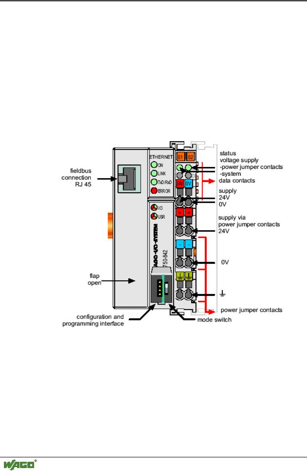
Connect the DC 24 V power supply unit 787-602 to the supplies (24 V and 0 V) for the controller and the power jumper contacts (see Fig.1).
In this example it would be sufficient to bridge “24V“ and “+“ or “0V“ and “-“.
Fig. 1: 10 MBit ETHERNET fieldbus controller 750-842
WAGO-I/O-SYSTEM 750
ETHERNET StarterKit 1
Quick Start |
• 9 |
Ethernet Network Start-Up
2.2 Ethernet Network Start-Up
Connect the fieldbus node to your Ethernet network.
Either connect it directly to a PC using a crossover cable (crossed Ethernet cables) or to a Hub or a Switch using a 1-to-1 patch cable.
Please write down the following Ethernet settings of your PC: the IP address (e.g. 192.168.1.1), the subnet mask (e.g. 255.255.0.0) and possibly the gateway IP address.
You can see the settings under Start Æ Settings Æ Network and Dialup Connections.
Your network administrator can give you more information.
Write down the MAC ID of the controller 750-842 which you can find on the barcode sticker or on the circuit diagram on the back of the controller.
Install the ”WAGO BootP Server“ which you can find on the “ELECTRONICC Tools and Docs“ CD (Item No.: 0888-0412/0001-0101) or on the Internet under: www.wago.com Æ Service Æ Downloads Æ Software.
Click the “Edit Bootptab“ button. Create an entry in the bootptab file with the following structure:
”Any name“ : ht=1 : ha= ”MAC Id of the coupler“ : ip= ”New IP address of the coupler“ : sm= ”Subnet mask“
Example:
Wago:ht=1:ha=0030DE001234:ip=192.168.1.2:sm=255.255.0.0:
Activate the BootP server by clicking on the “Start“ button and then disconnect the fieldbus node from the voltage supply for about 2 seconds. At each startup, the 750-842 controller sends a BootP request to the network. When the BootP server receives that request, it searches the “bootptab“ file for the assigned hardware address. After an entry has been found, the BootP server sends the IP address, subnet mask and gateway address with BootP response to the controller. Then the controller stores the assigned IP address and can be accessed immediately at this address.
After each power-on, the controller keeps on asking for an IP address by sending BootP requests. However, if no BootP response is received by the 750-842 controller, the last-assigned IP address will be used.
This behavior differs from that of the 750-841 controller, which requires the presence of a BootP server when the BootP is activated.
To store the IP address permanently, the BootP request must be zeroed. This setting can be done using the "EthernetSettings.exe" tool.
WAGO-I/O-SYSTEM 750
ETHERNET StarterKit 1
10 • Quick Start
Ethernet Network Start-Up
Note
The permanent storage of the IP address for the ETHERNET fieldbus controller 750-842 is achieved in a different way as it is the case with the ETHERNET fieldbus controller 750-841.
Note
When DHCP servers are used in the same network, there is a risk that a new IP address might be automatically allocated to the 750-842 controller after power-on, since BootP requests are sent by the controller after power-on. This can only be avoided by disabling the BootP requests.
Disabling the BootP requests is done using the ”WAGO EthernetSettings“ tool, which you can find on the “ELECTRONICC Tools & Docs“ CD (Item No.: 0888-0412/0001-0101) or on the Internet at: www.wago.com
Leave the controller turned on and turn off the BootP Server.
Start a browser (e.g. Internet Explorer, Netscape Navigator).
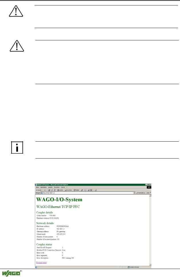
Enter the IP address of the controller 750-842 into the address bar of your browser (e.g. http://192.168.1.2).
The Proxy server should be avoided for local addresses.
Further information
Please find more information about avoiding the Proxy server in the browser help section under ”Proxy server“ and ”LAN settings“.
The integrated Web server will now create a Web page (no data can be entered).
WAGO-I/O-SYSTEM 750
ETHERNET StarterKit 1