Материал: m0842qs1e
Quick Start • 11
Ethernet Network Start-Up
Fig. 2: Web server 750-842 ”WAGO-Ethernet TCP/IP PFC”, status information
WAGO-I/O-SYSTEM 750
ETHERNET StarterKit 1
12 • Quick Start
The First Program
2.3 The First Program
Prerequisite:
The WAGO-I/O-PRO CAA software (CoDeSys) has to be installed correctly and started.
You can start a new project via Æ File Æ New.
Example:
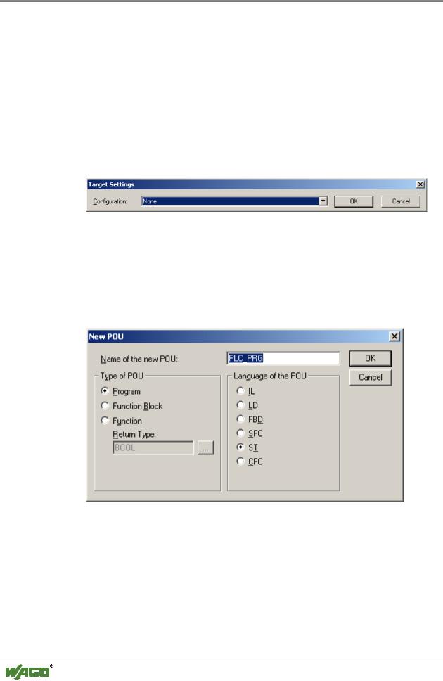
Before programming the 750-842 controller, select the controller in the “Target Settings“ window.
Fig. 3: Target settings
Please select the “WAGO_750-842_DEMO“ target in this window.
Then confirm the selected target with “OK“ in the dialog box above.
A POU can now be created in the following dialog box. In this example, a new “PLC_PRG“ is created in “ST“ programming language (Fig. 4).
Fig. 4: WAGO-I/O-PRO CAA, creating a new POU
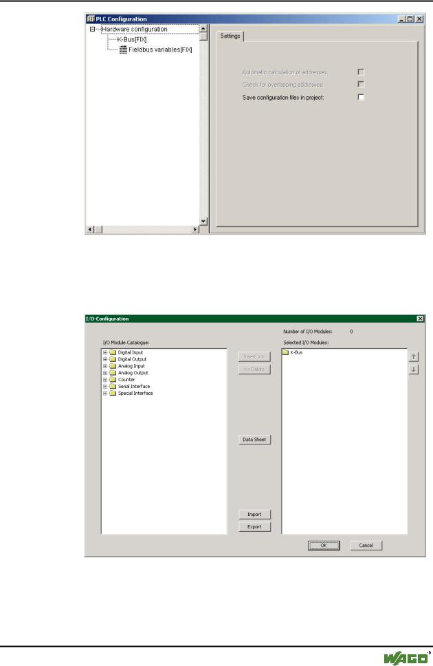
Before starting to create a POU, a PLC configuration must be performed.
To do so, change to PLC configuration in the “Resources“ register.
WAGO-I/O-SYSTEM 750
ETHERNET StarterKit 1
Quick Start • 13
The First Program
Fig. 5: WAGO-I/O-PRO CAA, PLC configuration
In the PLC configuration, first select “K-Bus[FIX]“, then right-click the mouse to open the context menu and select ”Append sub-element“. This will open the I/O configuration window.
Fig. 6: WAGO-I/O-PRO CAA, I/O configuration
In the application example shown in section 2.1, a single 750-430 digital input module has been connected to the 750-842 controller, followed by a 750-530 digital output module. The 750-600 end module is arranged on the very right hand side.
WAGO-I/O-SYSTEM 750
ETHERNET StarterKit 1
14 • Quick Start
The First Program
In the I/O module catalog on the left, first click on “Digital Input” to select the 750-430 module and then move the module to the right into your selection using the “Insert“ button.
Then, select the 750-530 module from the I/O module catalog on the left by clicking on “Digital Output” and move it to the right into your selection using the “Insert“ button.
If you wish to delete some modules from your selection, select the appropriate module on the right-hand side and click the ”Delete“ button.
You can change the position of a module in your selection by selecting and moving the module using the up and down arrow buttons on the right-hand side of the window.
The 750-600 end module is not shown in the I/O configuration window.
Then confirm your selection with “OK“.
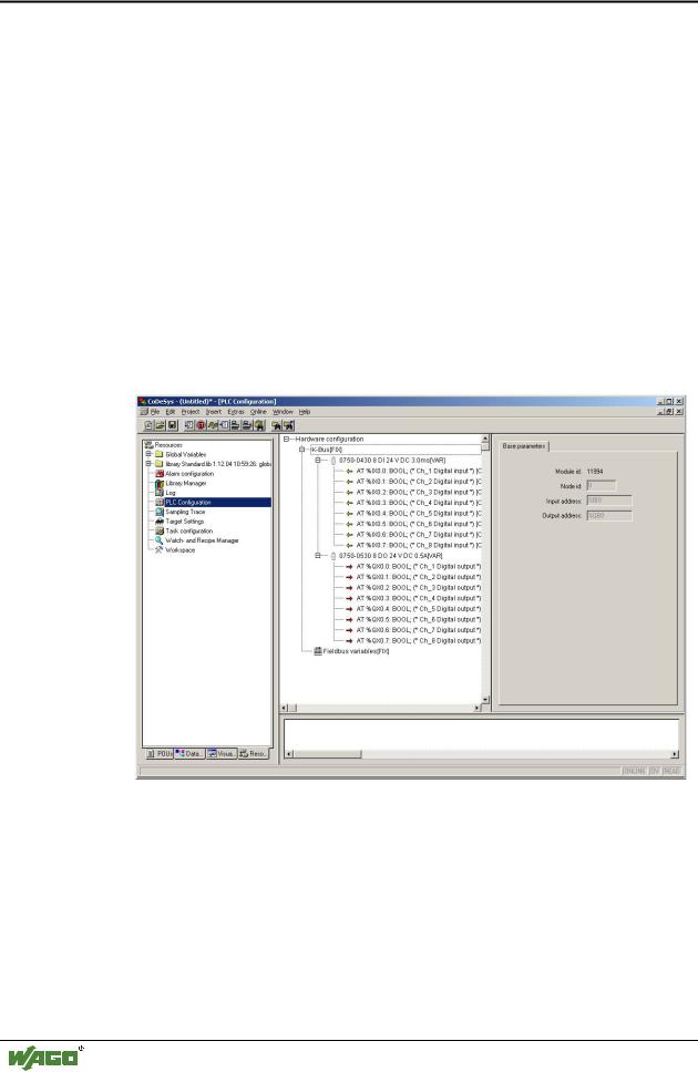
Fig. 7: WAGO-I/O-PRO CAA, I/O configuration with 750-430 and –530
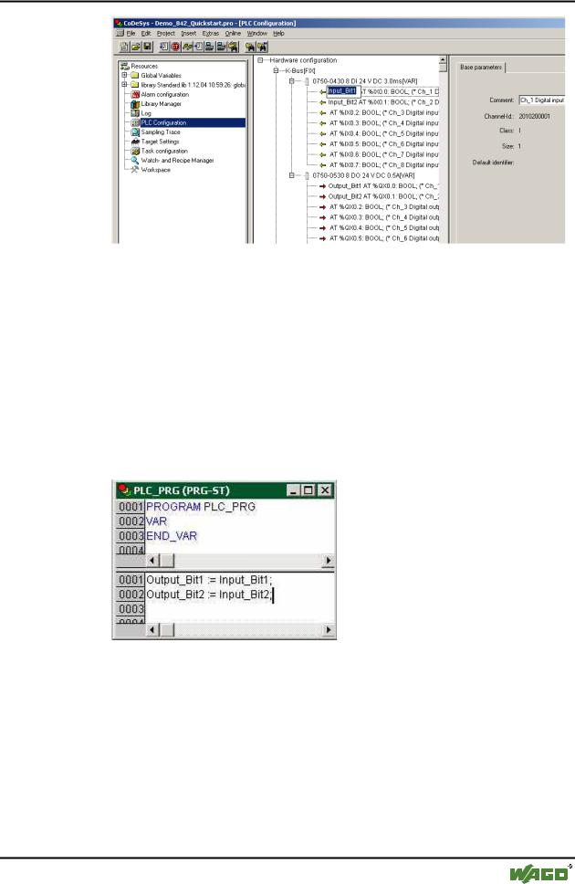
The I/O configuration window now shows the address of each channel, and thus each individual bit on the module.
Left clicking on the arrow next to “AT“ will open a text box in which you can enter a variable name (Fig. 8).
WAGO-I/O-SYSTEM 750
ETHERNET StarterKit 1
Quick Start • 15
The First Program
Fig. 8: WAGO-I/O-PRO, Declaration of variables with I/O configuration dialog
Now enter the following variable names:
Input_Bit1 (for the %IX0.0 address)
Input_Bit2 (for the %IX0.1 address)
Output_Bit1 (for the %QX0.0 address)
Output_Bit2 (for the %QX0.1 address)
Then, open the “PLC_PRG“ program from the “POUs“ register and complete a simple assignment within the statement part of the program:
Output_Bit1 := Input_Bit1;
Output_Bit2 := Input_Bit2;
Fig. 9: WAGO-I/O-PRO CAA,
Declaration and statement part of the PLC-PRG program
This way, both the first two inputs and first two outputs are assigned to each other (Fig. 9).
The program can now be loaded if the test program has been successfully compiled.
Compilation is initiated via Æ Project Æ Rebuild all.
WAGO-I/O-SYSTEM 750
ETHERNET StarterKit 1