Материал: m0842qs1e
16 • Quick Start
Program Download to the 750-842 Controller
2.4 Program Download to the 750-842 Controller
Click Æ Online Æ Communication parameter in the menu and create a new communication channel.
Choose Ethernet_TCP_IP (WAGO Ethernet TCP/IP driver).
Enter the IP address of the coupler under “IP Address“ (e.g. 192.168.1.2). Enter port number 2455. The transport protocol is TCP.
Please note that the simulation is deactivated.
You can now download the program via Æ Online Æ Login.
Start the program via Æ Online Æ Run.
Note
It is not possible to store programs permanently using the demo version of WAGO-I/O-PRO; i.e. the program must be downloaded and started anew after a power failure.
2.5Alternative to the Variable Declaration in the PLC Configuration
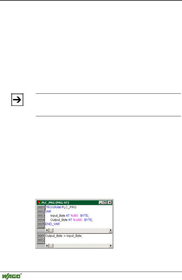
Instead of addressing bits individually and globally in the PLC configuration, a whole byte can also be addressed locally in the declaration part of the “PLCPRG“ program.
Open the “PLC_PRG“ program under the “POUs“ register and declare the local process image as follows:
Input_Byte |
AT |
%IB0: |
BYTE; |
Output_Byte |
AT |
%QB0: |
BYTE; |
Fig. 10: WAGO-I/O-PRO CAA,
Declaration and statement part of the PLC-PRG program
WAGO-I/O-SYSTEM 750
ETHERNET StarterKit 1

Quick Start • 17
Modbus/TCP DLL Application Examples
A simple assignment in the statement part of the program could be:
Output_Byte := Input_Byte;
This way, the inputs are assigned to the outputs (Fig. 10).
The program can now be loaded if the test program has been successfully compiled.
Compilation is activated via Æ Project Æ Rebuild all.
(Continue in section 2.4 “Program Download to the 750-842 Controller”)
2.6 Modbus/TCP DLL Application Examples
Before you can use the Modbus/TCP-DLL, it needs to be installed on your computer (preferably in the Windows System directory).
Restart your computer.
You can find a DLL function description in the API Modbus/TCP DLL manual, chapter 2.1 ff, which is on the “WAGO DLL Modbus/TCP“ CDROM (759-312).
In the “Samples” directory you will find examples for DLL applications under VBA, VB6, Delphi5, vb.net, VC++6, C#, LabVIEW7
An updated list is available from our support center.
WAGO-I/O-SYSTEM 750
ETHERNET StarterKit 1

18 • Addressing
Address Ranges of the 750-842 Controller
3 Addressing
3.1 Address Ranges of the 750-842 Controller
3.1.1 Word Access
|
Method |
|
Modbus |
Modbus |
IEC1131 |
Description |
|
|
|
addresses |
addresses |
addresses |
|
|
FC3 |
|
0... |
0x0000 – |
%IW0... |
Phys. inputs |
|
– Read Multiple Register |
|
255 |
0x00FF |
%IW255 |
|
|
(read data word by word) |
|
256... |
0x0100 – |
%QW256... |
PFC-OUT variables |
|
|
|
511 |
0x01FF |
%QW511 |
|
|
|
|
512 ... |
0x0200 – |
%QW0... |
Phys. outputs |
|
|
|
767 |
0x02FF |
%QW255 |
|
|
|
|
768 ... |
0x0300 – |
%IW256... |
PFC-IN variables |
|
|
|
1023 |
0x03FF |
%IW511 |
|
|
|
|
Illegal address |
0x0400 – |
Not supported |
|
|
|
|
range |
0x0FFF |
|
|
|
|
|
4096... |
0x1000 – |
Not supported |
Configuration register |
|
|
|
8191 |
0x1FFF |
|
(see annex 3.2 |
|
|
|
|
|
|
or manual) |
|
|
|
8192 ... |
0x2000 - |
Not supported |
Firmware register |
|
|
|
12287 |
0x2FFF |
|
(see annex 3.2 |
|
|
|
|
|
|
or manual) |
|
|
|
12288... |
0x3000 - |
%MW0... |
RETAIN variables |
|
|
|
16384 |
0x3FFF |
%MW4095 |
|
|
FC16 |
|
0... |
0x0000 – |
%QW0... |
Phys. outputs |
|
– Write Multiple Register |
|
255 |
0x00FF |
%QW255 |
|
|
(write data word by word) |
|
256... |
0x0100 – |
%IW256... |
PFC-IN variables |
|
|
|
511 |
0x01FF |
%IW511 |
|
|
|
|
512... |
0x0200 – |
%QW0... |
Phys. outputs |
|
|
|
767 |
0x02FF |
%QW255 |
|
|
|
|
768 ... |
0x0300 – |
%IW256... |
PFC-IN variables |
|
|
|
1023 |
0x03FF |
%IW511 |
|
|
|
|
Illegal address |
0x0400 – |
Not supported |
|
|
|
|
range |
0x0FFF |
|
|
|
|
|
4096... |
0x1000 – |
Not supported |
Configuration register |
|
|
|
8191 |
0x1FFF |
|
(see manual) |
|
|
|
Illegal address |
0x2000 - |
Not supported |
Firmware register |
|
|
|
range |
0x2FFF |
|
(see manual) |
|
|
|
12288... |
0x3000 - |
%MW0... |
RETAIN variables |
|
|
|
16383 |
0x3FFF |
%MW4095 |
|
WAGO-I/O-SYSTEM 750
ETHERNET StarterKit 1

|
|
|
|
|
|
|
|
|
|
|
Addressing |
• 19 |
|
|
|
|
|
|
|
Address Ranges of the 750-842 Controller |
|
||||||
|
|
|
|
|
|
|
|
|
|
|
|
|
|
3.1.2 Bit Access |
|
|
|
|
|
|
|
|
|
|
|
|
|
|
|
|
|
|
|
|
|
|
|
|
|
|
|
|
Method |
|
Modbus |
|
|
Modbus |
|
|
IEC1131 |
|
|
Description |
|
|
|
|
addresses |
|
|
addresses |
|
|
addresses |
|
|
|
|
|
FC2 |
|
0... |
|
|
0x0000 – |
|
|
%IX( DigitalOffSet + 0 ).0 ... |
|
|
Phys. inputs |
|
|
- Read Input Discrete |
|
511 |
|
|
0x01FF |
|
|
%IX( DigitalOffSet + 31).15 |
|
|
|
|
|
(read data bit by bit) |
|
512... |
|
|
0x0200 – |
|
|
%QX( DigitalOffSet + 0 ).0 ... |
|
|
Phys. outputs |
|
|
FC1 = FC2 + 0x0200 |
|
1023 |
|
|
0x03FF |
|
|
%QX( DigitalOffSet + 31).15 |
|
|
|
|
|
|
Illegal address |
|
|
0x0400 – |
|
|
Not supported |
|
|
|
|
|
|
– Read Coils |
|
range |
|
|
0x0FFF |
|
|
|
|
|
|
|
|
(read data bit by bit with |
|
4096... |
|
|
0x1000 – |
|
|
%QX256.0 ... |
|
|
PFC-OUT variables |
|
|
address offset of 0x0200, |
|
8191 |
|
|
0x1FFF |
|
|
%QX511.15 |
|
|
|
|
|
used to read back |
|
|
|
|
|
|
|
|
|
|
|
|
|
|
8192... |
|
|
0x2000 – |
|
|
%IX256.0 ... |
|
|
PFC-IN vriables |
|
|
|
output bits) |
|
|
|
|
|
|
|
|
||||
|
|
12287 |
|
|
0x2FFF |
|
|
%IX511.15 |
|
|
|
|
|
|
|
|
|
|
|
|
|
|
|
|
|||
|
|
|
12288... |
|
|
0x3000 - |
|
|
%MX0.0 .. |
|
|
RETAIN variables |
|
|
|
|
32767 |
|
|
0x7FFF |
|
|
%MX1274.15 |
|
|
|
|
|
|
|
Not supported |
|
|
Not supported |
|
|
%MX1275.0 .. |
|
|
|
|
|
|
|
|
|
|
|
|
|
%MX4095.15 |
|
|
|
|
|
FC15- |
|
0... |
|
|
0x0000 – |
|
|
%QX( DigitalOffSet + 0 ).0 ... |
|
|
Phys. outputs |
|
|
- Force Multiple Coils |
|
511 |
|
|
0x01FF |
|
|
%QX( DigitalOffSet + 31).15 |
|
|
|
|
|
(write data bit by bit) |
|
512... |
|
|
0x0200 – |
|
|
%QX( DigitalOffSet + 0 ).0 ... |
|
|
|
|
|
|
|
1023 |
|
|
0x03FF |
|
|
%QX( DigitalOffSet + 31).15 |
|
|
|
|
|
|
|
Illegal address |
|
|
0x0400 – |
|
|
Not supported |
|
|
|
|
|
|
|
range |
|
|
0x0FFF |
|
|
|
|
|
|
|
|
|
|
4096... |
|
|
0x1000 – |
|
|
%IX256.0 ... |
|
|
PFC-IN variables |
|
|
|
|
8191 |
|
|
0x1FFF |
|
|
%IX511.15 |
|
|
|
|
|
|
|
8192... |
|
|
0x2000 – |
|
|
%IX256.0 ... |
|
|
|
|
|
|
|
12287 |
|
|
0x2FFF |
|
|
%IX511.15 |
|
|
|
|
|
|
|
12288... |
|
|
0x3000 - |
|
|
%MX0.0 .. |
|
|
RETAIN variables |
|
|
|
|
32767 |
|
|
0x7FFF |
|
|
%MX1279.15 |
|
|
|
|
|
|
|
Not supported |
|
|
Not supported |
|
|
%MX1279.0 .. |
|
|
|
|
|
|
|
|
|
|
|
|
|
%MX4095.15 |
|
|
|
|
Notes:
The “DigitalOffSet“ of the digital inputs is 0, when no analog input modules / specialty modules and no ”SET_DIGITAL_INPUT_OFFSET“ POU (from the ”mod_com.lib“ library) are used.
The “DigitalOffSet“ of the digital outputs is 0, when no analog output modules / specialty modules and no “SET_DIGITAL_OUTPUT_OFFSET“ POU (from the “mod_com.lib“ library) are used.
Therefore, the following address spaces are available for the communication with a WAGO 750-842 Controller.
Address space |
Modbus |
PLC |
Description |
|
access |
access |
|
Phys. inputs |
read |
read |
Physical inputs (%IW0 ... %IW255) |
Phys. outputs |
read/write |
read/write |
Physical outputs (%QW0 ... %QW255) |
PFC-IN variables |
read/write |
read |
Volatile PLC input variables (%IW256 ... %IW511) |
PFC-OUT variables |
read |
read/write |
Volatile PLC output variables (%QW256 ... %QW511) |
Configuration register |
read/write |
--- |
See section 3.2 or manual |
Firmware register |
read |
--- |
See section 3.2 or manual |
RETAIN variables |
read/write |
read/write |
Remanent memory (%MW0 ... %MW4095) |
WAGO-I/O-SYSTEM 750
ETHERNET StarterKit 1

20 • Addressing
Address Ranges of the 750-842 Controller
In contrast to the WAGO 750-842 Controller, only the following address spaces are available for communication with a WAGO 750-342 Coupler.
Address space |
Modbus |
Description |
|
access |
|
Phys. inputs |
read |
Physical inputs (%IW0 ... %IW255) |
Phys. outputs |
read/write |
Physical outputs (%QW0 ... %QW255) |
Configuration register |
read/write |
See section 3.2 or manual |
Firmware register |
read |
See section 3.2 or manual |
WAGO-I/O-SYSTEM 750
ETHERNET StarterKit 1