Материал: Russian Journal of Building Construction and Architecture
Russian journal of building construction and architecture
а) |
b) |
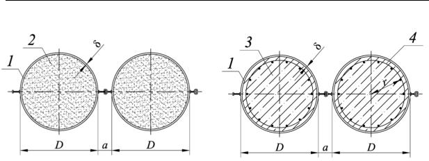
Fig. 3. Schemes of the sections of tubular welded walls:
а) a structure of tubular welded walls with a pipe filled with a sand-cement mix or a soil nuclear; b) a structure of a tubular welded piles with a tube filled with ferroconcrete;
1 — structure of tubular welded piles; 2 — sand-cement mix (soil nuclear); 3 — monolith ferroconcrete; 4 — reinforced frame
If pipes are filled with monolith concrete or ferroconcrete
A |
1000 |
A |
, I |
1000 |
I |
|
, |
(2) |
|
D a |
red |
|
D a |
|
red |
|
|
where Аred, Ired are the areas and moments of inertia approximated to steel of sections of the pipes determined using the following formula:
A |
|
D2 |
|
n |
1 |
A |
A |
, I |
|
|
D4 |
|
n |
|
1 |
I |
|
|
1 |
A r2 |
, |
(3) |
|
sb |
|
|
|
sb |
|
|
|
||||||||||||||
4n |
|
|
64n |
|
|
2 |
||||||||||||||||
red |
|
|
n |
|
D |
tot |
|
red |
|
|
|
n |
|
|
D |
|
tot |
|
|
|||
|
|
sb |
|
sb |
|
|
|
|
|
sb |
|
|
sb |
|
|
|
|
|
|
|
||
nsb = Еs/Eb is a ratio of the elasticity modules of steel and concrete; Atot is the area of the section of anoperatingreinforcementofferroconcreteusedfor;r istheradius ofareinforcedframe(Fig.3b). The calculation of a deepened part of the supporting wall relies on the following assumptions. 1. A deepened rod of finite stiffness replacing the supporting walls in a calculation scheme is divided into two parts: the upper one within which contact impact is determined with the limit resistance of рdeterm of the base and the lower one with a pressed, bent one according to the solution of a contact task using the method of elastic deformations.
The calculation is performed using the method of subsequent approximations with a step-wise displacement of the boundary between the above parts of a tubular welded wall. At the end of a calculation using the strength (in the first group) the height of a pressed part should be not less than ⅓ of the total height of the pressed part of the pile and not less than 5 m and at the end of the calculation using the displacements (the second group) is no less than ½ of the total height of the deepened part of the pile.
66
Issue № 2(34), 2017 |
ISSN 2542-0526 |
2. A force impact of the pressed part of the rod is assumed to interact with the soil environment and to be described with the function of the coefficient of the subbase Cz according to the equation
Cz KzО , |
(4) |
where K is the coefficient of the proportionality with the dimensionality kN/m4 depending on a type of a soil in accordance with the appendix V SP 24.13330.2011 of the size 1/3 of the values in Table В.1; zО is the coordinate of the length of the wall calculated from the surface of the base.
The coefficient of the subbase expresses the ratio of contact pressures рz and joint horizontal displacements уz of the pile and soil foundation:
Cz рz / уz . |
(5) |
The coefficient of proportionality can change at the boundary of geological layers in the base (Fig. 2). At the distance between the pipes а > 1,0 m the coefficient K is multiplied by the coefficient of the operating conditions:
с |
D 1 |
, |
(6) |
|
|||
|
D a |
|
|
where D and а retain its previous values and are expressed in meters. |
|
||
A horizontal load Рz per 1 meter of the width of the supporting wall is given by the ratio |
|
||
Рz рz 1 м Сz уz 1 м. |
(7) |
||
3. Contact pressures pz and the linear load Рz are restricted by corresponding limit values рdeterm, Рdeterm that are capable of perceiving the base:
pz pdeterm ,Pz Pdeterm . |
(8) |
The limit resistance of the base from the side of the front side of the piled supporting wall is determined as the difference between the passive pressure рp from the side of the front face and active pressure ра from the side of the back face of the supporting wall:
pdeterm pn pa |
(9) |
The limit linear load of the horizontal load on the base is as follows: |
|
Pdeterm pdeterm 1m (pn pa ) 1m. |
(10) |
4. The pressures рp and ра are identified based on the condition of the strength of the soil according to the Moht-Coulomb equation:
12 1 – 2 – 12 1 2 sin –c cos 0,
67
Russian journal of building construction and architecture
where σ1,2 the major stresses at the points (elementary volumes) of the soil on the contact (vertical) faces of the tubular piled supporting walls.
The fraction on the contact sides is neglected. Strains acting on these faces are major ones. The active ра and passive рp pressures of the soil on the vertical faces of the piled supporting walls is determined depending on the vertical pressure рv of the soil behind the lower supporting wall and natural pressure рzg of the soil of the base from the side of the front face of the supporting wall.
While determining the active pressure σ2 is replaced by ра, σ1 by на рv:
|
1 |
sin |
|
|
|
cos |
|
|
2 |
|
|
|
|
|
|
|
|
|
|
|
|
|
|
|
|
|
|
|
|
|
|||||||
pa pv |
|
|
|
2c |
|
|
|
pvtg |
|
|
45 |
|
|
2c tg |
45 |
|
. |
(11) |
1 |
sin |
1 |
sin |
|
2 |
2 |
||||||||||||
|
|
|
|
|
|
|
|
|
|
|
||||||||
While determining the passive pressure from the side of the front face of the supporting wall of the tubular welded pile in the base, σ1 is replaced by рп, σ2 by the natural pressure рzg:
|
1 |
sin |
|
|
|
cos |
|
|
2 |
|
|
|
|
|
|
|
|
|
|
|
|
|
|
|
|
|
|
|
|
|
|||||||
pn pzg |
|
|
|
2c |
|
|
|
pzg tg |
|
|
45 |
|
|
2c tg |
45 |
|
. |
(12) |
1 |
sin |
1 |
sin |
|
2 |
2 |
||||||||||||
|
|
|
|
|
|
|
|
|
|
|
||||||||
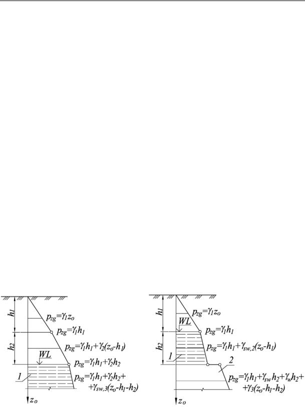
5. The distribution of the vertical pressure pzg from the weight of the soils of the base is accepted as specified in the schemes in Fig. 4 [7, 14]. In the upper layer as well as if the base is made more complicated by homogeneous soils with an evenly distributed specific weight,
pzg zО. |
(13) |
а) |
b) |
Fig. 4. Diagrams of the distribution of the vertical pressure pzg from eigen weight of the soils: а) in the bases with a varying specific weight along the depth if there are underground waters; b) in the bases partially weighed soil waters if there is a water-absorbing layer;
1 — water-absorbing soil; 2 — water-resistant layer of the base; WL is the level of underground waters
68
Issue № 2(34), 2017 |
ISSN 2542-0526 |
In the layer foundations with a varying specific weight and water absorbing soils if there are underground waters (Fig. 4а)
pzg |
1h1 |
2 |
(zО –h1), |
(14) |
|
pzg 1h1 2h2 sw,3(zО –h1 –h2), |
|||||
|
|||||
where h1, h2 are the thickness of the layers of the base within the depth zО; γ1, γ2 are specific weights of the bases of the layers of the base above the underground waters, γsw,3 is a specific weight of the layer of the water-absorbing soil determined as the weight of mineral particles, the indices 1, 2, 3 relate to the numbers of the layers of the soil.
In the water-absorbing layer of the bases the weight of the above layers and the weight of the layer of water are considered according to the scheme in Fig. 4b:
pzg 1h1 sw,2h2 wh2 3(zО – h1 – h2 ), |
(15) |
where γw = 9.8 kN/m3 is a specific weight of water, γ3 is a specific weight of the waterabsorbing layer.
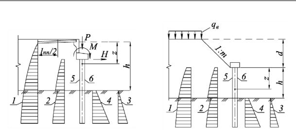
6. The distribution of the vertical pressures pv behind the face of the supporting wall of the abutment of a bridge (Fig. 5а) is determined according to the following formulas:
–– within the filling behind the abutment (above the level of the planned surface): |
|
pv пz, |
(16) |
where γп is a specific weight of the abutment soil; z is a vertical coordinate calculated from the top of the filling behind the abutment according to the scheme in Fig. 5а;
–– within the base (below the level of the planned surface):
(17) The distribution of the vertical pressures pv behind the lower face of a road supporting wall in Fig. 5b is given by the following formulas:
–– within the filling (above the level of the planned surface):
p n z popen , (18)
–– within the base (below the level of the planned surface):
p n h popen pzg , |
(19) |
where h is the height of the underground part of the supporting wall (Fig. 5b); popen is a vertical pressure of the soil behind the lower face of the supporting wall from the weight of the sloped part of the abutment with the height d distributed according to the below expressions (21) that were obtained in the following way.
69
Russian journal of building construction and architecture
а) |
b) |
Fig. 5. Distribution of the pressures рv (1), ра (2)
on the back (5) and рzg (3), рf (4) on the front (6) faces of the piled supporting walls
Let us denote the intensity of the distributed load at the level AB on the left from the point D (Fig. 6):
qopen nd qb . |
(20) |
where qв is a temporary vertical load that is agreed to be evenly distributed on the surface of the base according to the GOST 32960-2014.
The vertical strains рopen behind the back face of the supporting wall are determined depending on qopen using the following approach that is similar to that in construction mechanics (the method of boundary elements). The essence of this method is to agree to expand the calculation area to the size and shape where there are ready-made solutions and to apply new boundaries of such a system of forces so that the distribution of strains on an actual surface of the calculation area with an acting load.
Let us show an example. The calculation area and an acting load are replaced with the equivalent system where the level of a horizontal face AB is displaced to the top at the height of ½md into the position A’B’. The acting load of a trapezoid shape is replaced by a band with the intensity qopen and is placed according to the scheme in Fig. 6. The total weight of the sloping part of the abutment and the equivalent load replacing it.
Let us draw two rays from the point Е at the angle of 450. One of them crosses the point В and the other one the point F. Let us assume that at the level AB the intensity of the load on the left of the point F is q open and on the right of the point changes according to the linear law to zero at the point В. Then the shape of the distribution of the load coincides with an actual shape of a part of the abutment.
70