Материал: Russian Journal of Building Construction and Architecture
Issue № 2(34), 2017 |
ISSN 2542-0526 |
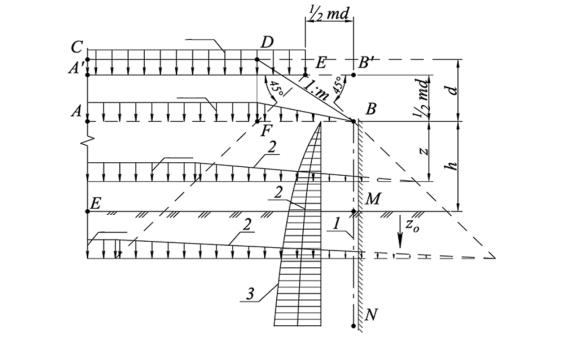
Let us assume that the effect of a band load in the system restricted with a horizontal plane A’B’ is the same as that of an actual load on the lower semi-space. Continuing both rays we get vertical strains on the line ВМN within the filling part of the calculation area:
|
|
|
|
|
|
qopen z /(md 2z), |
(а) |
within the base: |
|
||||||
|
|
|
|
qopen (h zo )/[md 2(h zo )]. |
(b) |
||
|
|
|
|
|
|
|
|
|
|
|
qopen |
|
|||
|
|
|
|
|
|
||
|
|
qopen |
|
||||
|
|
|
|
||||
|
qopen |
|
|||||
qopen
Fig. 6. Scheme of determining vertical strains behind the back supporting wall from the weight of the sloping part of the base:
1 — back face of the supporting wall;
2 — diagrams of distribution qopen z /(md 2z) and qopen (h zo )/(md 2(h zo )); 3 is a diageram of distribution of Рopen
The obtained expressions correspond with free distribution of strains in the soil without a supporting wall. If we neglect horizontal displacements of the supporting wall, the back face is considered supported. In order to obtain рopen “the imaging method” can be employed [11, p. 400] according to which under the effect of a one-sided system of the forces, a motionless wall is replaced by a symmetry plane. Hence in order to obtain рopen the expressions (а) and (b) should be doubled:
popen 2qopen z /(md 2z), |
(21) |
|
popen 2qopen (h zo )/[md 2(h zo )]. |
||
|
71
Russian journal of building construction and architecture
2. Sequence of the calculation. The calculations of supporting walls in accordance with the above guidelines should be performed using the finite element method. It is possible to use the software such as LIRA, SCAD, MicroFe, Midas civil or other verified (tested) software recommended for use in the Russian Federation. Calculations are performed in the below sequence.
1. Creating a finite element scheme [13—15] by dividing (in the underground and deepened parts) of a vertical rod depicting the pile supporting wall, on the finite elements with the step t of no more than 1 m and no more than 0.1 of the heights of the overand underground parts.
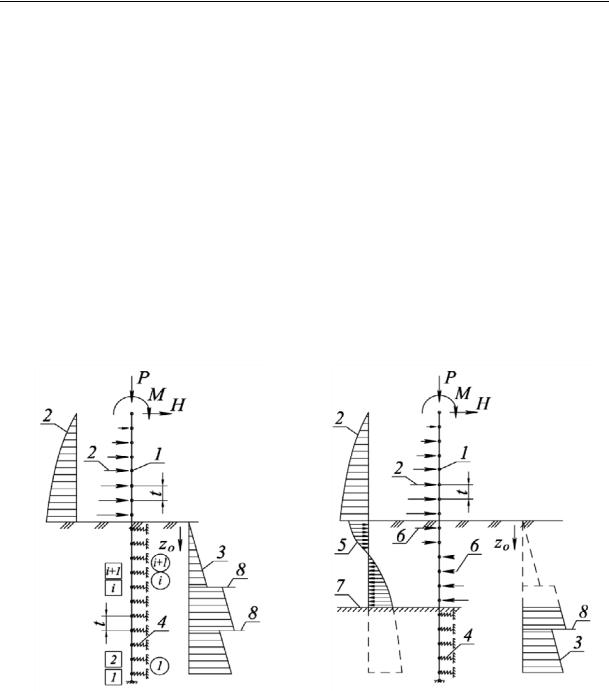
The coordinates and the number of the finite elements and nodes on their boundaries start from the lower end of the supporting wall (Fig. 7).
а) |
b) |
Fig. 7. Scheme of the calculations of the walls of the method of finite elements:
а) the first step of calculations (boundary of the pressed part at the level of the planned surface); b) the second and subsequent steps of the calculation; 1 — piled supporting wall;
2 — diagram ра and the force Fai in the overground part of the supporting wall; 3, 4 — diagram of the coefficient of the subbase Сz = KzО
and its replacement with conditional “spins” with the stiffness Вzi = Kj zОi t×1 m; 5, 6 — linear load Рdetermi and its replacement with the node forces Fdeterm
7 — boundary of the pressed part of the tubular welded pile;
8 — boundary of geological layers;  –– numbers of the nodes;
  — numbers of the finite elements
72
Issue № 2(34), 2017 |
ISSN 2542-0526 |
2. Replacing a triangular or stepwise diagram of distribution with the coefficient of the subbase with conditional horizontal stiff rods (“spins”) with the length of 1 m with the compressive and tension stiffness Вz = Сzt × 1 m. The conditional “spins” are placed into the nodes of the finite element system. The stiffness of the conditional spin in the i-th node:
(22) where zОi is the coordinate zО i-th node; Kj is the coefficient of proportionality of j-th layer of the base where there is the i-th node.
3. Applying a horizontal pressure ра to the nodes of the underground part of the back face of the tubular welded pile of the supporting wall. The load ра is transformed into the node forces of the force Fai using the formula
Fai pait 1m |
(23) |
where раi is the pressure ра at the level of the i-th node of the overground part of the supporting wall.
Determining equal horizontal forces Н and a moment М of loads applied to the head of the abutment and its application to the upper node of the system. There is no scuh operation in a road supporting wall.
4. Determining a specific linear horizontal load Рdeterm, i in the nodes of the pressed part:
Pdeterm,i (pni pai ) 1m |
(24) |
where рпi, раi are linear loads рп and ра at the level of the i-th node of the pressed piled supporting wall.
5. The first (initial) step. The boundary of the pressed part of the piled supporting wall is accepted to be at the level of the planned surface.
Designing and solving the system of equations of the method of finite elements expressing the balance of the nodes. The solution is horizontal displacements уzi and rotation angles φzi of the piled supporting wall in the nodes.
Determining the linear load in the nodes using the formula
Pzi pzi 1m yzi K j zoi 1m, |
(25) |
and node forces in the conditional “spins”: |
|
Rzi Рzit. |
(26) |
Comparing Рzi and Рdeterm, i in the nodes of the system, identifying nodes where Рzi > Рdeterm, i. Рzi ≤ Рdeterm, i, and displacing the boundary of the pressed part of the piled supporting wall by one level.
73

Russian journal of building construction and architecture
6. The second and subsequent steps. The level of the pressed part of the piled supporting wall based on the results of the previous step is identified in the node where Рzi ≤ Рdeterm, i. In the above nodes instead of Rzi the following loads are applied
Fdeterm,i Pdeterm,it (pni pai )t 1m. |
(27) |
Repeating calculations and logical operations with a new level of pressing and corrected loads.
The latter is the approximation where the ratios Рzi ≤ Рdeterm, i in the nodes of the system. Testing the conditions Рzi ≤ Рdeterm, i at all the levels of the pressed part of the tubular welded pile. 7. Calculation of the first group completes obtaining the node forces Rzi= Рzit in the conditional “spins”, designing the diagrams of longitudinal forces and moments for each combination of loads.
Calculation of the seconв group completes designing the axis of the piled supporting wall and determining a horizontal displacement in the node of the support of a span structure on the abutment (with combined functions) of a bridge structure for each combination of loads.
Calculations of structures of tubular pile in the composition of abutments of bridges and road supporting walls include the following tests performed in compliance with the current guideline (SP 35.13330, SP 24.13330, etc.)
The first group:
––calculation of longitudinal sections for bending or outercentral compression (if a piled system perceives a longitudinal force besides a horizontal pressure);
––calculation of the sections of a pipe on the longitudinal force by comparing calculation and tangent strains;
––calculation of the strength for a complex stress-strain in the sections of a pipe where there are both normal and tangent strains;
––calculation of the strength of circular sections of a ferroconcrete filling for bending and a longitudinal force;
––testing a tubular piled abutment using the bearing capacity of the base group.
The second group:
––testing of structures of deformation stitches and supporting parts on the capacity to perceive horizontal displacements of the abutments in joints with wardrobe walls and supporting nodes of bridges.
––comparing horizontal displacement of the upper road supporting wall with a specific value.
74
Issue № 2(34), 2017 |
ISSN 2542-0526 |
3. Сalculation example. Fig. 8 shows the section of a wall of tubular welded pile, the calculation scheme for the last displacement of the initial level and results of calculations of the supporting wall with the total length of 6.7 m supporting the soil in the road butt with the depth of 10 m. The label of a tubular welded pile is ShTS-820×13 ZSG1, the external diameter of the pipes is 820 mm, the thickness of the wall is 13 mm, the geometric characteristics are
A 0.0304m2 /m,I 0.0025m4 /m,W 0.0061m3 /m.
The label of steel is 09G2S-12 according to the GOST 19281-89*, calculation resistance Rу = 295 МPа, elasticity module Е = 2.06×10⁵ МPа. The bearing capacity of the tubular welded pile: in the moment Мdeterm = 1798 kNm/m, in the longitudinal force Qпред = 2727 kN/m.
The calculations were performed twice: the first group in the strength (the second using displacements) of the group using the calculation (normal) loads and mechanical characteristics of soils (Table). According to the above, the calculations were performed by means of the method of subsequent approximations with a stepwise displacement of the boundary of the pressed part of the piled supporting wall. At the first stage the boundary of the pressed part was placed at the level of the planned surface.
|
|
|
|
|
Table |
|
|
|
Mechanical characteristics of soils |
|
|
||
|
|
|
|
|
|
|
|
|
|
Standard/calculated |
|
|
|
Name of the soil |
|
|
|
|
||
Specific adhesion |
Angle of the internal friction |
Specific weight, |
K, |
|||
|
|
|||||
|
|
Cnorm/cinvestig, kPa |
Φnorm./φinvestig degrees |
Γnorm./γinvestig, kN/m3 |
kN/m4 |
|
|
|
|
|
|
|
|
1. |
Solid loam |
26.2/17.5 |
23.2/20.2 |
18.2/18.0 |
6000 |
|
|
|
|
|
|
|
|
2. |
Soft plastic loam |
15.0/14.0 |
17.0/16.0 |
18.8/18.7 |
2800 |
|
|
|
|
|
|
|
|
3. |
Stiff plastic clay |
33.0/32.0 |
18.0/17.0 |
18.6/18.6 |
4680 |
|
|
|
|
|
|
|
|
4. |
Semi-stiff clay |
36.0/36.0 |
19.0/18.0 |
18.7/18.0 |
5720 |
|
|
|
|
|
|
|
|
In the calculation using the strength 5 steps of reducing the pressing boundary was necessary followed by determining it at the level of 9.0 m from the planned surface and 7.3 m from the lower end of the tubular welded pile. In the calculation using the displacemetns the pressing boundary was obtained on the planned surface at the first stage of the calculation.
The results of the calculation are presented in Fig. 8c: digrams of contact pressures, moments (horizontal displacements) according to the results of the calculations of the first (second)
75