Материал: Russian Journal of Building Construction and Architecture
Issue № 2(34), 2017 |
ISSN 2542-0526 |
According to the same law, the bending moments in the clutch of the span in the fourth of the span are distributed;
Fluctuation of the normal efforts in the clutch section of the arch is considerably different from the normal law. Identical deviation from the normal law is characteristic of the bending moment in the support section of the arch;
2. If a deviation of the bending moment in the support section of the arch has a negative asymmetry and values, large mathematical expectations of the value, have high probabilities, i.e. normal conditions in the clutch section of the arch have a positive asymmetry, large mathematical anticipation of the value, have low probabilities.
The use of the obtained data on the effect of a range of the deformation modulus Е on the cal-
culation efforts Sр in the typical sections of the arch depends on the distribution law of certain
efforts Si. If this factor is normal, the expression for a specific degree known in the reliability theory can be employed:
S p ms · s , |
(3) |
where β is the correction number of the standards. With a specific degree Р = 0.95 this parameter is accepted to be β = 1.64.
For deviations of the distributions of the evaluated parameters on the normal law the calculation efforts were calculated using fractiles of the chosen betadistribution using the mathematical software MathCAD.
The results of computing the calculation parameters of the efforts in the typical sections of the arch for the investigated example using the above calculation algorithms are listed in Table.
Data on the probabilistic calculations of efforts in the typical sections of the arch |
Table |
||||||
|
|||||||
|
Section |
|
|
Calculation characteristics |
|
||
Effort |
Mathematical |
|
Variation |
Distributuion, |
Calculation |
||
of the arch |
Standard |
||||||
|
anticipation |
coefficient |
asymmetry |
value |
|||
|
|
|
|
|
|
|
|
|
Support |
–348.5 |
1.79 |
0.51 |
Normal |
–349.3 |
|
|
Ка = –0.249 |
||||||
|
|
|
|
|
|
||
Normal |
Fourth of |
–267.7 |
1.32 |
0.48 |
Normal |
–274.4 |
|
Ка = 0.399 |
|||||||
effort, kN |
the span |
|
|
|
|
||
|
Clutch |
–447.8 |
0.54 |
0.18 |
Betalaw |
–447.9 |
|
|
Ка = –1.008 |
||||||
|
|
|
|
|
|
||
|
Support |
–18.2 |
0.35 |
1.9 |
Betalaw |
–18.8 |
|
|
Ка = –0.906 |
||||||
Bending |
|
|
|
|
|
||
Fourth of |
8.1 |
0.81 |
10 |
Normal |
9.4 |
||
moment, kNm |
|||||||
|
the span |
|
|
|
Ка = 0.399 |
|
|
|
Clutch |
–40.4 |
0.90 |
2.2 |
Normal |
41.9 |
|
61

Russian journal of building construction and architecture
Conclusions
The analysis of the results of the probabilistic calculations of the efforts in the typical sections of the arch listed in Table resulted in the following conclusions:
1. A deviation of the moments for most characteristics of the sections of bridges using a sandy filling considering fluctuations of the deformation module of the soil filling is insignificant, which is important for considering possible defects and damage [5]. Even with the variation coefficient of the deformation module νЕ = 31 % a deviation of normal efforts in all of the sections does not exceed 0.5 % and the fluctuation of the bending moments in most loaded by bending and clutch sections is 1.9—2.2 %. It is only in the fourth of the span where the bending moments are considerably lower that the variation coefficient is 10 %.
2. While conducting strength calculations of the arch ferroconcrete shells in the elastic environment, determined specification of the elasticity module will suffice.
References
1.Safronov V. S., Zazvonov V. V. Vliyanie deformatsionnykh kharakteristik peschanoy zasypki na nap- ryazhenno-deformirovannoe sostoyanie gruntozasypnykh mostov [The influence of the deformation characteristics of the sand backfill on the stress-strain state Protosenya bridges]. Stroitel'naya mekhanika i konstruktsii, 2010, no. 1, pp. 16––21.
2.Safronov V. S., Zazvonov V. V. Vliyanie temperaturnykh vozdeystviy na napryazhenno-deformirovannoe sostoyanie bessharnirnykh svodchatykh proletnykh stroeniy gruntozasypnykh mostov [The influence of temperature effects on stress-strain state hingeless vaulted spans Protosenya bridges]. Nauchnyy vestnik Voronezhskogo GASU. Stroitel'stvo i arkhitektura, 2011, no. 1 (21), pp. 107—116.
3.Safronov V. S., Zazvonov V. V. Raschetno-eksperimental'noe issledovanie napryazhenno-deformirovannogo sostoyaniya zhelezobetonnogo svoda gruntozasypnogo avtodorozhnogo mosta [Numerical and experimental investigation of the stress-strain state of reinforced concrete arch highway bridge groundshaking]. Stroitel'naya mekhanika inzhenernykh konstruktsiy i sooruzheniy, 2011, no. 2, pp. 49—55.
4.Safronov V. S., Domanov D. I. Otsenka vliyaniya kosiny proletnykh stroeniy zhelezobetonnykh mostov na risk razrusheniya normal'nykh secheniy balok s nenapryagaemym armirovaniem ot izgibayushchego momenta [Assessment of the impact of skew span structures of reinforced concrete bridges on the risk of fracture normal sections beams free of tension reinforcement from the bending moment]. Stroitel'naya mekhanika i konstruktsii, 2012, vol. 2, no. 4, pp. 85—91.
5.Safronov V. S., Petranin A. A., Petrenya E. N. Superelementnyy raschet v smeshannoy postanovke zhelezobetonnykh mostov, imeyushchikh defekty i povrezhdeniya [Super-element calculation in a mixed setting of concrete bridges with defects and damages]. Izvestiya vuzov. Stroitel'stvo, 1996, no. 6, pp. 103—110.
6.Seredin P. V., Glotov A. V., Domashevskaya E. P. e. a. Structural and optical investigations of AlxGa1xAs:Si/GaAs(100)MOCVD heterostructures.PhysicaB-condensedMatter,2010,vol.405,iss.22,pp.4607––4614.
62

Issue № 2(34), 2017 |
ISSN 2542-0526 |
UDC 624.014.27 : 624.046
D. M. Shapiro1, A. P. Tyutin2, V. A. Rodionov3
THEORY AND DESIGN SCHEME
OF ROAD ENGINEERING STRUCTURES FROM PIPE GROOVE
Voronezh State Technical University
Russia, Voronezh, tel.: +7-910-344-73-34, e-mail: davshap@mail.ru 1D. Sc. in Engineeting, Prof. of the Dept. of Structural Mechanics Ltd. «Center-Dorservis»
Russia, Voronezh, e-mail: cds@cds.vrn.ru 2PhD in Engineering, Leading engineer 3Leading engineer
Statement of the problem. Designing a welded tubular pile is a new competitive variety of retaining walls used in modern construction. Developing calculation method for designing and investigating such systems is an important issue.
Results. The article provides a description and algorithms of the developed method of calculating engineering structures from pipe groove within road engineering structures. The theoretical basics, description of design diagrams, sequence of the calculation by means of the finite element method, a set of tests to limit state are presented. A calculation example is given.
Conclusions. The solution of practical problems and algorithmization of calculation tribosphenic systems within the road engineering structures is obtained. The results of the study are suitable for use in calculations of other designs of flexible retaining walls of groove type.
Keywords: welded tubular pile, calculation, design, road retaining walls, bridge foundations.
Introduction
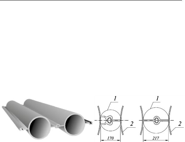
The last decade has seen engineering structures developing into a new direction when enveloping systems starting emerging as support walks from tubular welded piles [1—4, 6, 9, 10, 12, 17, 20]. They consist of a steel pipe and welded clutched joints (Fig. 1). An internal vacuum of the pipe is filled with sand-cement mix (5:1 ratio), monolith ferroconcrete or soil nuclear that is designed considering the length within the base.
© Shapiro D. М., Tuytin А. P., Rodionov V. А., 2017
63
Russian journal of building construction and architecture
The advantages of tubular welded piles is a high level of ready-made quality, strength and simplicity of aligned joints, suitability for quick construction and operation in severe climate conditions. All of these make them particularly attractive for the use in construction as well as road industry: edge supports of bridges, supporting walls of the base, ramp areas of tonnels and other types of enveloping systems.
In the guidelines [5, 8, 16—19] there are theoretical foundations and general principles of calculating piled supporting walls requiring specification and extra information to be employed in projects. This article deals with practical tasks and algorithms of the developed engineering method of calculation for designing and studying engineering structures using tubular welded pipes.
а) |
b) |
Fig. 1. Structure of a tubular welded pile:
а) schemes of elements of welded tubular piles; b) examples of highly efficient clutch joints 1 [10]; 2 — tube
1. Theoretical foundations and description of calculation schemes. Calculations of road engineering structures are performed using limit states in two groups in accordance with GOST 27751-2014: in the first group (strength and bearing capacity) using calculation loads and strength characteristics of soils, in the second group (using transformations) by means of normal laods and strength characteristics of soils.
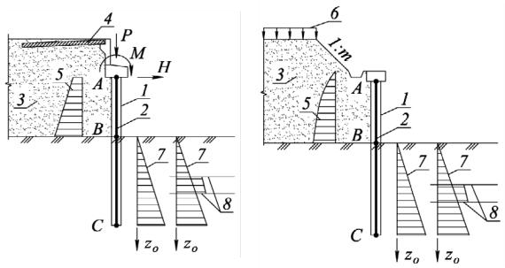
Calculations are performed in accordance with the conditions of a flat task (flat deformation). The calculation area (Fig. 2) is a segment of a designed structure with the width of 1 m restricted side vertical faces. Calculation schemes of tubular pile supporting walls 1 are replaced with flat rods of finite stiffness 2 with the calculation width of 1 m consisting of two areas: underground АВ and deepened into the base ВС.
The area АВ takes the active pressure of the soil from the side of the back face of a tubular welded pile, loads Р, Н, М applied to the head of an abutment (Fig. 2а) and eigen weight of supporting wall structures.
64
Issue № 2(34), 2017 |
ISSN 2542-0526 |
а) |
b) |
Fig. 2. Calculation schemes of road engineering structures using tubular welded piles: а) of an abutment of a bridge; b) of a road supporting wall;
1 — abutment (supporting wall); 2 — flat rod; 3 — filling behind the abutment, base of the road; 4 — intermediate plate; 5 — diagram of the active pressure of the soil; 6 —time road vertical load; 7 — distribution of the coefficient of the subbase Сz = KzО in a homogeneous and layer bases; 8 — boundaries of geological layers
The deepened lower part of the wall ВС is an operating area interacting with the base transmitting a horizontal and momentous loads. In order to describe a force impact of the soil and deepened part of tubular welded piles, a calculation scheme is used that combines the theory of the method of local elastic deformations with a triangular shapes of the distribution of the coefficient of the subbase and limit stress-strain of the soil.
The geometric characteristics of the sections are: area А, сm2/m, moment of inertia I, сm4/m, moment of resistance W, сm3/m, in extra calculations per 1 p. m. of a tubular welded pipes are determined depending on identical parameters of the sections of the pipes.
As the pipes are filled with a sand-cement mix or a soil nuclear
A |
1000 A |
, I |
1000 I |
|
, W |
1000 W |
, |
(1) |
|
D a D |
|
D a |
D |
|
D a D |
|
|
where АD, ID, WD are geometric characteristics of the sections of vacuum pipes with the thickness of the walls δ considering losses caused by corrosion; D and a are the sizes, mm (Fig. 3а).
65