Материал: Russian Journal of Building Construction and Architecture
Issue № 2(34), 2017 |
ISSN 2542-0526 |
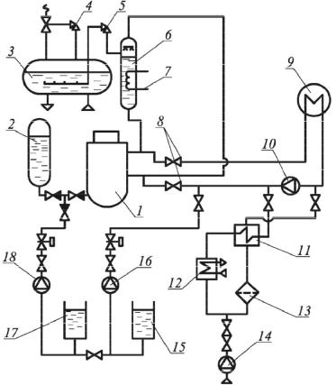
The first contour (Fig. 3) consists of a reactor 1 with four parallel loops (in Fig. there is one loop), each of which includes a steam generator 9, the main circulating pump (MCP) 10, the main isolation valves 8 main circulation pipelines where the organization of several parallel loops makes redundancy of equipment in particular of circulation pumps unnecessary. The water in the reactor is supplied at the pressure of 16.6 MPa with the temperature of 562 K. In the core it is heated up to 595 and is sent to the steam generator where it is cooled giving heat to the secondary coolant. The boiler water enters the main circulation pump which returns it to the reactor. Between the reactor and steam generator there are the main isolation valves that can shut off any loop from the reactor. MCP is installed on the disconnected part of the "cool" pipeline. To create the required pressure for a steam compensator (SC) 6, the steam condensator is used. It also serves to compensate for volume changes of the coolant by heating it at the circuit and the initial pressure. Water in is heated by the heaters 7 and partially vaporized resulting in the necessary pressure. SC is connected to a hot pipe on the side that is kept switched on.
Fig. 3. Scheme of the first circuit of NPP with the reactor VVER-1000:
1 is a reactor; 2 is an accumulator; 3 is a bubbler; 4,5 are safety valves; 6 is a pressure compensator; 7 is a heater; 8 are the main isolation valves; 9 is a steam generator; 10 is a reactor coolant pump; 11 is a heat exchanger; 12 is a refrigerator; 13 is a filter; 14, 16, 18 are pumps; 15, 17 are tanks with boric acid solution
21

Russian journal of building construction and architecture
To prevent the pressure SC from exceeding the allowable into the steam space, heat is injected from the cool part of the pipeline. If the injection of the cool keeps resulting in an increase in the pressure, safety valve 5 opens, the output of which is connected to a bubble counter 3. The water temperature in the bubbler is maintained at ~333 K for condensing steam from SC. If the bubbler pressure increases above acceptable, the safety valve 4 in the bubbler will switch on and the heat carrier will be emitted from the first circuit.
The water of the first circuit when the reactor obtains a highly induced radioactivity, as there are always impurities that are activated in the active area. As a result, the first circuit equipment becomes a source of ionizing radiation and thus is placed in unattended areas. To clean the heat carrier off impurities a part of it (a so-called purging) with the flow rate of 22 kg/s with the pressure side coolant is diverted into the filter 13. Before entering the filters, the purge water is cooled down to 318 K. Cooling occurs due to the heating of the purified water in the regenerative heat exchanger 11, after which the filter returns to the loop in the suction branch of the MCP. The final cooling of the purge water is performed using technical water in the fridge 12. Compensation for the losses of the first coolant and the first filling of the circuit produces a charging pump 14 of the special system of the preparation of pure capacitors. Nuclear facilities are equipped with systems of emergency cooling of the active zone of the reactor (ECCS) that provide heat removal from the reactor in case of accidents with the loss of the first coolant. In emergency situations, when the loss of coolant occurs at a slow speed, high pressure pumps are included. At significant depressurization, up to the full instantaneous rupture of a circulation pipe, at first the water is supplied from the accumulator, then high pressure pumps are included, and, if their supply is not enough to maintain the pressure in the circuit a low-pressure pump starts operating.
2. Schematic diagram of the nuclear stations of heat supply. The most cost-efficient use of nuclear fuel is achieved when applied to nuclear power plants. However, in some cases the use of nuclear stations of a heat supply is economically justified. The purpose of the ACT is the production of heat for household and business needs.
The feasibility of the construction of the AST is determined by the following factors:
1)significant facilitation of the conditions for the selection of construction sites for ACT that do not require water resources and additional investments for the construction of systems of technical water supply;
2)great radiation safety of AST compared to the ACEP that allows it to be located at a inconsiderable distance from the consumer;
22
Issue № 2(34), 2017 |
ISSN 2542-0526 |
3)vicinity of AST allows one to avoid significant heat losses during transportation of a heat carrier, to reduce the costs for pumping of a coolant (design of the study the ATEC shows that the costs of transit heat networks is approximately 15 % of the that of the plant);
4)a relatively small value of the required area, less environmental pollution by harmful emissions at the normal and emergency modes of operation.
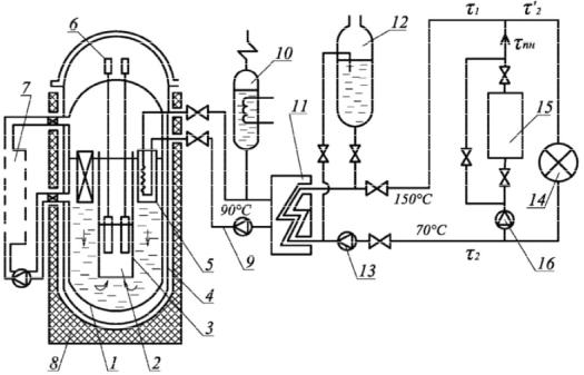
One of the possible methods of increasing the effectiveness of the AST is to increase the coefficient of the use of its installed capacity that can be achieved by the co-joint operation of AST and peak water-heating boiler stations which provide a covering of the graph of peak thermal load. Providing this part of the graph of the heat load with a peak of sources allows one to increase the duration of the operation of AST at its rated power and to reduce the influence of daily fluctuations of load of hot water supply for its operation mode. The efficiency and reliability of the AST depends on the choice of rational modes of its operation along with peak boilers that must generally be located in the center of thermal loads. In this case, there are two possible schemes of the connection of AST and a peak boiler: the serial and the parallel one. A thermal scheme of the ACT with parallel of a peak boiler is shown in Fig. 4.
Fig. 4. Scheme of a nuclear power station heating:
1 is a reactor vessel; 2 is a core; 3 is a mine of the contour of a natural circulation; 4 is a safety body; 5 is heat exchanger of the second circuit; 6 is the shutoffs of the control system control and reactor protection; 7 are extra systems of the first circuit; 8 is a ferroconcrete shaft; 9 is the second circuit; 10 is a volume compensator; 11 is network heat exchanger; 12 is a system of emergency cooling; 13 is a pump; 14 is a heat consumer;
15 is a peak boiler; 16 are the pumps of the peak boiler
23

Russian journal of building construction and architecture
For the ACT a corpus of pressurized water reactor as more reliable compared to the channel water-graphite reactor. The relatively low pressure inside the reactor leads to a significantly smaller load on the wall and roof of the body of the reactor. To improve the reliability there is a so-called safety case, the main purpose of which is the prevention of coolant leakage of the heat carrier in case of depressurization of the body of the reactor. The concrete shaft is mainly designed to protect against radiation, but it allows one to take additional measures to prevent leaks of the first heat carrier into soil. The heat carrier of the third circuit circulates in the central heating system of residential and public buildings after mixing with water coming from a peak boiler connected with the AST.
Conclusions
1.The thermal schemes of nuclear power plants of heat supply and atomic heat and power plants as well as the parameters of the basic units examined in the article can be used as a source for searching the most optimal modes of operation to allow one to determine the ways of improving the basic circuits of nuclear power plants as a result of more in-depth analysis.
2.An increase in the cost efficiency of nuclear stations of heat supply is possible when they operate jointly with peak boilers located in the centre of thermal loads. At the same time it should be noted that the vicinity of the stations from the city determines higher requirements for the reliability of the station.
References
1.Ignatov V. I. e. a. Heatand Neutron-Physical Characteristics of Power-Generating Units of Nuclear Power Plants with Vver-1000 during Operation Above Nominal Power: (for the Example of the No. 2 Unit of the Balakovo Nuclear Power Plant). Atomic Energy, 2009, no. 1 (107), pp. 9—17.
2.Gorlinskii Yu. E. e. a. Securing the Radiological Safety of People and the Environment at All Stages of the Life Cycle of Float-ing Nuclear Heat-and-Power Plants. Atomic Energy, 2009, no. 2 (107), pp. 122—129.
3.Aminov R. Z., Beresh V. T. Safety Assessment of a Nuclear Power Plant with Gas-Turbine Back-up for Internal Needs. Atomic Energy, 2004, no. 6 (96), pp. 434—438.
4.Sokolov A. S. Numerical Simulation of the Thermal Conditions in a Sea Bay Water Area Used for Ater Supply to Nuclear Power Plants. Power Technology and Engineering, 2013, no. 2 (47), pp. 139—142.
5.Gagarinski A. Bilibino Heat and Power for Russia’S Northern Regions. Nuclear Engi-neering International, 1995, no. 40, pp. 14—15.
6.McDonald C. F. Mobile Hybrid (Nuclear/Oil Fired) Gas Turbine Cogeneration Power Plant Concept. Applied Thermal Engineering, 1998, no. 6 (18), pp. 353—368.
24
Issue № 2(34), 2017 |
ISSN 2542-0526 |
7.Mel'kumov V. N., Kuznetsov I. S., Kobelev V. N. Zadacha poiska optimal'noy struktury teplovykh setey [The task of finding the optimal structure of heat networks]. Nauchnyy vestnik Voronezhskogo GASU. Stroitel'stvo i arkhitektura, 2011, no. 2, pp. 37—42.
8.Medvedevа O. N. The Selection of Gas Pipeline Route on the Plan of Gas Supplied Area. Scientific Herald of the Voronezh State University of Architecture and Civil Engineering. Con-struction and Architecture, 2011, no. 3, pp. 26—35.
9.Mel'kumov V. N., Chuykin S. V., Papshitskiy A. M., Sklyarov K. A. Modelirovanie struktury inzhenernykh setey pri territorial'nom planirovanii goroda [Modeling of the structure of utility networks the regional planning city]. Nauchnyy vestnik Voronezhskogo GASU. Stroitel'stvo i arkhitektura, 2015, no. 2 (38), pp. 41—48.
10.Miram O. Teplosnabzhenie ot atomnykh istochnikov [Heat supply from nuclear sources]. Santekhnika, otoplenie, konditsionirovanie, 2010, no. 7 (103), pp. 48—49.
11.Puzakov V. S. Teplosnabzhenie ot AES v Evrope [Heat supply from nuclear power in Europe].
Santekhnika, otoplenie, konditsionirovanie, 2013, no. 3 (135), pp. 60—63.
12.Bocharov V. L., Smirnova A. Ya., Bugreeva M. N. Vliyanie atomnykh teplo- i elektrostantsiy na geologicheskuyu sredu (Tsentral'no-chernozemnyy ekonomicheskiy rayon) [The effect of atomic heat and power plants in the geological environment (the Central black earth economic region)]. Vestnik Voronezhskogo gosudarstvennogo universiteta. Geologiya, 1996, no. 1, pp. 165—171.
13.Mel'kumov V. N., Kuznetsov C. N., Sklyarov K. A., Gorskikh A. A. Monitoring nadezhnosti teplovykh setey [Monitoring the reliability of thermal networks]. Nauchnyy vestnik Voronezhskogo GASU. Stroitel'stvo i arkhitektura, 2010, no. 1, pp. 52—58.
14.Muramovich V. G., Petukhov V. V., Skorokhodov D. A. Al'ternativa plavuchim atomnym teploelektrostantsiyam [The alternative of floating nuclear power plants]. Al'ternativnaya energetika i ekologiya, 2014, no. 18 (158), pp. 65—69.
15.Grimes R. W., Nuttall W. J. Generating the Option of a Two-Stage Nuclear Renaissance. Science, 2010, no. 329, pp. 799—803.
16.Mel'kumov V. N., Kuznetsov I. S., Kobelev V. N. Vybor matematicheskoy modeli trass teplovykh setey [The choice of the mathematical model tracks thermal networks]. Nauchnyy vestnik Voronezhskogo GASU. Stroitel'stvo i arkhitektura, 2011, no. 2, pp. 31—36.
17. Seredin P. V., Glotov A. V., Ternovaya V. E. e. a. Spinodal decomposition of Ga (x) In1-x As (y) P1-y quaternary alloys. Semiconductors, 2011, vol. 45, iss. 11, pp. 1433––1440.
25